
INTERNATIONAL EDITION---Engineering Mechanics: Statics, 14th edition (SI unit)
14th Edition
ISBN: 9780133918922
Author: Russell C. Hibbeler
Publisher: PEARSON
expand_more
expand_more
format_list_bulleted
Videos
Textbook Question
Chapter 2.3, Problem 2PP
Then establish the triangle rule to show FR = FU + FV. Label all known and unknown sides and interior angles.
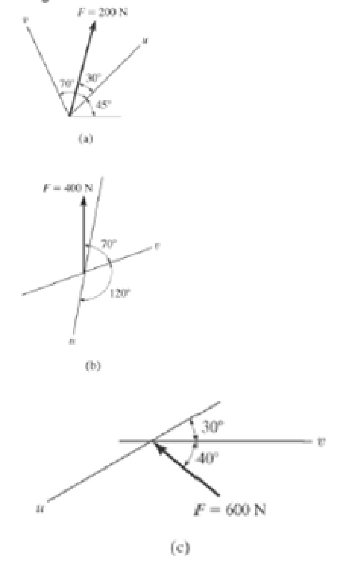
Prob. P2-2
Expert Solution & Answer

Learn your wayIncludes step-by-step video

schedule08:09
Students have asked these similar questions
A piston-cylinder device initially contains 0.08 m^3 of nitrogen gas at 130
kPa and 170°C. The nitrogen is expanded to a pressure of 80 kPa via
isentropic expansion. Determine the final temperature and the boundary
work done by the system during this process.
A Carnot (ideal) heat pump is to be used to heat a house and maintain it at 22°C
in winter. On a day when the average outdoor temperature remains at about 0°C,
the house is estimated to lose heat at a rate of 65,000 kJ/h. If the heat pump
consumes 6 kW of power while operating, determine:
(a) how long the heat pump ran on that day
(b) the total heating costs, assuming an average price of 11¢/kWh for electricity
(c) the heating cost for the same day if an 85% efficient electric furnace is used
instead of a heat pump.
From the information in the image, I needed to find the orientation of U relative to Q in vector basis q_hat. I transformed the euler angle/axis representation to euler parameters. Then I got its conjugate in order to get the euler parameter in N frame relative to Q. The problem gave the euler angle/axis representation in Q frame relative to N, so I needed to find the conjugate. Then I used the euler parameter rule of successive rotation to find the final euler parameters that describe the orientation of U relative to Q. However that orientation is in n_hat which is the intermediate frame. How do I get the final result in q_hat?
Chapter 2 Solutions
INTERNATIONAL EDITION---Engineering Mechanics: Statics, 14th edition (SI unit)
Ch. 2.3 - Then establish the triangle rule, where FR = F1 +...Ch. 2.3 - Then establish the triangle rule to show FR = FU +...Ch. 2.3 - Determine the magnitude of the resultant force...Ch. 2.3 - Determine the magnitude of the resultant force....Ch. 2.3 - Determine the magnitude of the resultant force and...Ch. 2.3 - Resolve the 30-lb force into components along the...Ch. 2.3 - Resolve this force into components acting along...Ch. 2.3 - along the v axis. Prob. F2-6Ch. 2.3 - If = 60 and F = 450 N, determine the magnitude of...Ch. 2.3 - If the magnitude of the resultant force is to be...
Ch. 2.3 - Determine the magnitude of the resultant force FR...Ch. 2.3 - Determine the magnitudes of the two components of...Ch. 2.3 - Solve with F = 350 lb. Prob. 2-4/5Ch. 2.3 - Determine the magnitude of the resultant force FR...Ch. 2.3 - Resolve the force F1 into components acting along...Ch. 2.3 - Resolve the force F2 into components acting along...Ch. 2.3 - If the resultant force acting on the support is to...Ch. 2.3 - Determine the magnitude of the resultant force and...Ch. 2.3 - If = 60, determine the magnitude of the resultant...Ch. 2.3 - Also, what is the magnitude of the resultant...Ch. 2.3 - Resolve this force into two components acting...Ch. 2.3 - Determine the magnitude of F and its component...Ch. 2.3 - Determine the magnitude of F and its direction ....Ch. 2.3 - Determine the required angle (0 45) and the...Ch. 2.3 - Determine the magnitude and direction of the...Ch. 2.3 - Determine the magnitude and direction of the...Ch. 2.3 - What is the component of force acting along member...Ch. 2.3 - Take = 30. Probs. 2-19/20Ch. 2.3 - FR measured counterclockwise from the positive x...Ch. 2.3 - Solve I by first finding the resultant F = F2 + F3...Ch. 2.3 - If F1 = 400 N and F2 = 600 N, determine the angle...Ch. 2.3 - If their lines of action are at an angle apart...Ch. 2.3 - If F1 = 30 lb and F2 = 40 lb, determine the angles...Ch. 2.3 - Determine the magnitude and direction of FA SO...Ch. 2.3 - Determine the magnitude and direction, measured...Ch. 2.3 - What is the minimum magnitude of FR?Ch. 2.3 - directed along the positive x axis, determine the...Ch. 2.3 - If FB = 3 kN and = 45, determine the magnitude of...Ch. 2.3 - If the resultant force of the two tugboats is...Ch. 2.4 - Resolve each force acting on the post into its x...Ch. 2.4 - Determine the magnitude and direction of the...Ch. 2.4 - Determine the magnitude of the resultant force...Ch. 2.4 - determine the magnitude of F and its direction ....Ch. 2.4 - If the magnitude of the resultant force acting on...Ch. 2.4 - Determine the magnitude of the resultant force and...Ch. 2.4 - Determine the magnitude of the resultant force and...Ch. 2.4 - Determine the magnitude of the resultant force and...Ch. 2.4 - Resolve F1 and F2 into their x and y components.Ch. 2.4 - Determine the magnitude of the resultant force and...Ch. 2.4 - Resolve each force acting on the gusset plate into...Ch. 2.4 - Determine the magnitude of the resultant force...Ch. 2.4 - Express each of the three forces acting on the...Ch. 2.4 - Determine the x and y components of F1 and F2....Ch. 2.4 - Determine the magnitude of the resultant force and...Ch. 2.4 - Determine the magnitude of the resultant force and...Ch. 2.4 - Express F1, F2, and F3 as Cartesian vectors.Ch. 2.4 - Determine the magnitude of the resultant force and...Ch. 2.4 - Determine the magnitude of the resultant force and...Ch. 2.4 - Determine the magnitude and direction of the...Ch. 2.4 - Determine the magnitude and orientation of FB so...Ch. 2.4 - measured counterclockwise from the positive y...Ch. 2.4 - Prob. 48PCh. 2.4 - Prob. 49PCh. 2.4 - Express F1, F2, and F3 as Cartesian vectors.Ch. 2.4 - Determine the magnitude of the resultant fore and...Ch. 2.4 - Show that the resultant force is zero. Prob. 2-52Ch. 2.4 - Express F1 and F2 as Cartesian vectors.Ch. 2.4 - Determine the magnitude of the resultant force and...Ch. 2.4 - What is the magnitude of the resultant force?...Ch. 2.4 - If the magnitude of the resultant force acting on...Ch. 2.4 - Set = 30. Probs. 2-56/57Ch. 2.4 - Determine the magnitude and direction of F so...Ch. 2.4 - Prob. 59PCh. 2.6 - Show , , . a) F = {50i + 60j 10k} kN b) F = {40i ...Ch. 2.6 - In each case, establish F as a Cartesian vector,...Ch. 2.6 - Set up the calculation used to find the magnitude...Ch. 2.6 - Determine the coordinate direction angles of the...Ch. 2.6 - Express the force as a Cartesian vector. Prob....Ch. 2.6 - Express the force as a Cartesian vector. Prob....Ch. 2.6 - Express the force as a Cartesian vector. Prob....Ch. 2.6 - Express the force as a Cartesian vector. Prob....Ch. 2.6 - Determine the resultant force acting on the hook....Ch. 2.6 - Determine the magnitudes of the x, y, z components...Ch. 2.6 - If the magnitude of F is 80 N, and = 60 and =...Ch. 2.6 - The component of F in the x-y plane is 7 kN. Prob....Ch. 2.6 - Determine the magnitude and coordinate direction...Ch. 2.6 - Specify the coordinate direction angles of F1 and...Ch. 2.6 - Express each force in Cartesian vector form and...Ch. 2.6 - Determine the coordinate direction angles of F1....Ch. 2.6 - Determine the magnitude and coordinate direction...Ch. 2.6 - Determine the magnitude and coordinate direction...Ch. 2.6 - Determine the magnitude and coordinate direction...Ch. 2.6 - Determine the magnitude and coordinate direction...Ch. 2.6 - Note that F1 lies in the x-y plane.Ch. 2.6 - If the resultant force FR has a magnitude of 150...Ch. 2.6 - Express each force in Cartesian vector form.Ch. 2.6 - Determine the magnitude and coordinate direction...Ch. 2.6 - Express each force as a Cartesian vector.Ch. 2.6 - Determine the resultant of the two forces and...Ch. 2.6 - Determine the magnitude and coordinate direction...Ch. 2.6 - Prob. 78PCh. 2.6 - Determine the coordinate direction angles of the...Ch. 2.6 - Express each force in Cartesian vector form and...Ch. 2.6 - If the coordinate direction angles for F1 are 3 =...Ch. 2.6 - If the coordinate direction angles for F1 are 3 =...Ch. 2.6 - If the direction of the resultant force acting on...Ch. 2.6 - Prob. 84PCh. 2.6 - If = 75, determine the magnitudes of F and Fy....Ch. 2.8 - In each case, establish a position vector from...Ch. 2.8 - In each case, express F as a Cartesian vector....Ch. 2.8 - Express the position vector rAB in Cartesian...Ch. 2.8 - What is the angle ? Prob. F2-20Ch. 2.8 - Prob. 21FPCh. 2.8 - Express the force as a Cartesian vector. Prob....Ch. 2.8 - Determine the magnitude of the resultant force at...Ch. 2.8 - Determine the resultant force at A. Prob. F2-24Ch. 2.8 - Determine the length of the connecting rod AB by...Ch. 2.8 - Express force F as a Cartesian vector; then...Ch. 2.8 - Express each of the forces in Cartesian vector...Ch. 2.8 - If F = {350i 250j 450k} N and cable AB is 9 m...Ch. 2.8 - Prob. 90PCh. 2.8 - If z = 5 m, determine the location +x, +y of point...Ch. 2.8 - Express each of the forces in Cartesian vector...Ch. 2.8 - If FB = 560 N and FC = 700 N, determine the...Ch. 2.8 - If FB = 700 N, and FC = 560 N, determine the...Ch. 2.8 - Express each force as a Cartesian vector. Prob....Ch. 2.8 - Represent each force as a Cartesian vector. Probs....Ch. 2.8 - Determine the magnitude and coordinate direction...Ch. 2.8 - Express the force as a Cartesian vector. Prob....Ch. 2.8 - Express this force as a Cartesian vector acting on...Ch. 2.8 - Determine the magnitude and coordinate direction...Ch. 2.8 - Represent each force as a Cartesian vector and...Ch. 2.8 - The anticipated loading in two of the struts is...Ch. 2.8 - Determine the magnitude and coordinate direction...Ch. 2.8 - If the force in each cable tied to the bin is 70...Ch. 2.8 - Due to symmetry, the tension in the four cables is...Ch. 2.9 - Do not calculate the result. Prob. P2-8Ch. 2.9 - P2.9. In each case, set up the dot product to find...Ch. 2.9 - Determine the angle between the force and the...Ch. 2.9 - Determine the angle between the force and the...Ch. 2.9 - Determine the angle between the force and the...Ch. 2.9 - Determine the projected component of the force...Ch. 2.9 - Find the magnitude of the projected component of...Ch. 2.9 - Determine the components of the force acting...Ch. 2.9 - Determine the magnitudes of the components of the...Ch. 2.9 - Express the force F in Cartesian vector form if it...Ch. 2.9 - Express force F in Cartesian vector form if point...Ch. 2.9 - If the force in each chain has a magnitude of 60...Ch. 2.9 - If the resultant force at O has a magnitude of 130...Ch. 2.9 - Determine the length of the chain, and express the...Ch. 2.9 - Determine the length of the cable and express the...Ch. 2.9 - Prob. 112PCh. 2.9 - Determine the magnitudes of the components of F =...Ch. 2.9 - Determine the angle between the two cables. Prob....Ch. 2.9 - Determine the magnitude of the projection of the...Ch. 2.9 - Determine the angle between the y axis of the...Ch. 2.9 - Determine the magnitudes of the projected...Ch. 2.9 - Determine the angle between cables AB and AC....Ch. 2.9 - Prob. 119PCh. 2.9 - Determine the magnitude of the projected component...Ch. 2.9 - Determine the angle between the two cables...Ch. 2.9 - Determine the angle between the cables AB and AC....Ch. 2.9 - Determine the magnitude of the projected component...Ch. 2.9 - Determine the magnitude of the projected component...Ch. 2.9 - Determine the magnitude of the projection of force...Ch. 2.9 - Determine the magnitude of the projected component...Ch. 2.9 - Determine the angle between pipe segments BA and...Ch. 2.9 - Prob. 128PCh. 2.9 - Determine the magnitude of the projected component...Ch. 2.9 - Determine the angles and made between the axes...Ch. 2.9 - Prob. 131PCh. 2.9 - Express this component as a Cartesian vector....Ch. 2.9 - Prob. 133PCh. 2.9 - Prob. 134PCh. 2.9 - Determine the magnitudes of the components of the...Ch. 2.9 - Determine the magnitudes of the projected...Ch. 2.9 - Prob. 137PCh. 2.9 - Determine the angle between the two cables....Ch. 2.9 - Express the result as a Cartesian vector.Ch. 2.9 - Determine the magnitude of the resultant force FR...Ch. 2.9 - Resolve F into components along the u and v axes...Ch. 2.9 - Determine the magnitude of the resultant force...Ch. 2.9 - Prob. 4RPCh. 2.9 - The cable attach to the tractor at B exerts a...Ch. 2.9 - Prob. 6RPCh. 2.9 - Determine the angle between the edges of the...Ch. 2.9 - Determine the projection of the force F along the...
Additional Engineering Textbook Solutions
Find more solutions based on key concepts
Write an SQL query to list each customer who bought at least one product that belongs to product line Basic in ...
Modern Database Management
Draw the shear and moment diagrams for the beam, and determine the shear and moment throughout the beam as func...
Mechanics of Materials (10th Edition)
For the circuit shown, use the node-voltage method to find v1, v2, and i1.
How much power is delivered to the c...
Electric Circuits. (11th Edition)
How is the hydrodynamic entry length defined for flow in a pipe? Is the entry length longer in laminar or turbu...
Fluid Mechanics: Fundamentals and Applications
Although it is kind of silly, state legislatures have been known to pass laws that change the value of pi. Supp...
Java: An Introduction to Problem Solving and Programming (8th Edition)
Suppose an amateur programmer writes a program for his or her own use and in doing so is sloppy in the programs...
Computer Science: An Overview (13th Edition) (What's New in Computer Science)
Knowledge Booster


Learn more about
Need a deep-dive on the concept behind this application? Look no further. Learn more about this topic, mechanical-engineering and related others by exploring similar questions and additional content below.Similar questions
- A proposed method of power generation involves collecting and storing solar energy in large artificial lakes a few meters deep, called solar ponds. Solar energy is absorbed by all parts of the pond, and the water temperature rises everywhere. The top part of the pond, however, loses much of the heat it absorbs to the atmosphere, and as a result, the cool surface water serves as insulation for the bottom part of the pond and helps trap the energy there. Usually, salt is planted at the bottom of the pond to prevent the rise of this hot water to the top. A heat engine that uses an organic fluid, such as alcohol, as the working fluid can be operated between the top and the bottom portions of the pond. If the water temperature is 27°C near the surface and 72°C near the bottom of the pond, determine the maximum thermal efficiency that this power plant can have. Treat the cycle as an ideal heat engine. Would a heat engine operating under these temperature conditions (27°C and 72°C) be…arrow_forwardA standard Carnot heat engine cycle is executed in a closed system between the temperature limits of 320 and 1350 K, with air as the working fluid. The pressures before and after the isothermal compression are 150 and 300 kPa, respectively. Sketch the TS diagram for this cycle. If the net work output per cycle is 0.75 kJ, determine the efficiency of the cycle and the heat transfer to the air (working fluid) per cycle.arrow_forwardPROBLEM 10: A sleeve in the form of a circular tube of length L is Nut placed around a bolt and fitted between washers at each end. The nut is then turned until it is just snug. Use material properties as follows: For the sleeve, as = 21 x 106/°C and Es = 100 GPa Washer Bolt ·L· Sleeve Bolt head For the bolt, αB = 10 × 10-6/°C and EB = 200 GPa. 1. Calculate the temperature rise that is required to produce a compressive stress of 25 MPa in the sleeve.arrow_forward
- This problem illustrates that the factor of safety for a machine element depends on the particular point selected for analysis. Here you are to compute factors of safety, based upon the distortion-energy theory, for stress elements at A and B of the member shown in the figure. This bar is made of AISI 1006 cold-drawn steel and is loaded by the forces F = 1.100 kN, P = 8.00 kN, and T = 50.00 N·m. Given: Sy = 280 MPa. B -100 mm- 15-mm D. a) What is the value of the axial stress at point A? b)What is the value of the shear stress at point A? c)Determine the value of the Von Mises stress at point A. P Farrow_forwardThe three steel wires, each of cross-sectional area 0.05 in2, support the weight W. Theirunstressed lengths are 74.98 ft, 74.99 ft, and 75.00 ft. Use E = 29 x 106 psi.1. Find the stress (psi) in the longest wire if W = 1500 lb.2. Determine the stress in the shortest wire if W = 500 lb ANSWERS: 6130 psi; 6930 psiarrow_forward1: The concrete column is reinforced using four steel reinforcing rods, each having a diameter of 18 mm. Determine the stress in the concrete and the steel if the column is subjected to an axial load of 800 kN. Est = 200 GPa, Ec = 25 GPa. Complete fbd.arrow_forward
- 5: As shown, two aluminum rods AB and BC, hinged to rigid supports, arepinned together at B to carry a vertical load P = 6000 lb. If each rod has a crosssectional area of 0.60 in2 and E = 10 x 106 psi. Use α = θ = 30⁰. Calculate the change in length (in) of rod AB and indicate if it elongates orshortens. Calculate the vertical displacement of B (in) and horizontal displacement of B (in). Complete fbd.arrow_forward2: The rigid bar supports the uniform distributedload of 6 kip/ft. Determine the force in each cable if each cable has a cross-sectional area of 0.05 in^2 , and E = 31(10)^3 ksi.arrow_forwardIn (Figure 1), take m₁ = 4 kg and mB = 4.6 kg. Determine the z component of the angular momentum Ho of particle A about point O. Determine the z component of the angular momentum Ho of particle B about point O. Suppose that 5 m 8 m/s 4 m 1.5 m 4 m B MB 1 m 2 m 5 30° 6 m/s MAarrow_forward
- The two disks A and B have a mass of 4 kg and 6 kg, respectively. They collide with the initial velocities shown. The coefficient of restitution is e = 0.75. Suppose that (VA)1 = 6 m/s, (VB)₁ = 7 m/s. (Figure 1) Determine the magnitude of the velocity of A just after impact. Determine the angle between the x axis and the velocity of A just after impact, measured clockwise from the negative x axis. Determine the magnitude of the velocity of B just after impact. Determine the angle between the x axis and the velocity of B just after impact, measured clockwise from the positive x axis. (VB)1 B (VA)1 60° Line of impactarrow_forwardA hot plane surface is maintained at 100°C, and it is exposed to air at 25°C.The combined heat transfer coefficient between the surface and the air is 25W/m²·K. (same as above). In this task, you are asked to design fins to cool asurface by attaching 3 cm-long, 0.25 cm-diameter aluminum pin fins (thermalconductivity, k = 237 W/m·K) with a center-to-center distance of 0.6 cm. (Tip:do not correct the length). Determine the rate of heat transfer from thefinned structure to the air for a 1 m x 1 m section of the plate.arrow_forwardHeat is generated uniformly in a 4 cm-diameter, 16-cm long solid bar (k=2.4 W/m-K). The temperaturesat the center and at the surface of the bar are measured to be 210 oC and 45 oC, respectively. Calculatethe rate of heat generation within the bar. Solve the relevant energy balance equation and the boundaryconditions to calculate the rate of heat generation within the bar. (6 pts)arrow_forward
arrow_back_ios
SEE MORE QUESTIONS
arrow_forward_ios
Recommended textbooks for you
 International Edition---engineering Mechanics: St...Mechanical EngineeringISBN:9781305501607Author:Andrew Pytel And Jaan KiusalaasPublisher:CENGAGE L
International Edition---engineering Mechanics: St...
Mechanical Engineering
ISBN:9781305501607
Author:Andrew Pytel And Jaan Kiusalaas
Publisher:CENGAGE L
How to balance a see saw using moments example problem; Author: Engineer4Free;https://www.youtube.com/watch?v=d7tX37j-iHU;License: Standard Youtube License