
Concept explainers
Videos
Assume
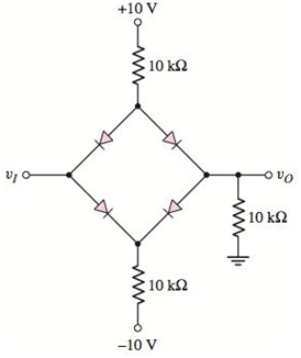
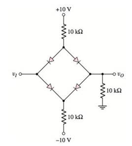
Figure P2.51
To plot: The output voltage,
Explanation of Solution
Given:
Calculation:
Case 1:
Assume that diodes
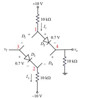
Figure 1
Apply the Kirchhoff’s voltage to the outer branch of the circuit shown in figure 1.
Therefore,
The voltage at node
The voltage at node
Apply the Kirchhoff’s voltage to the input branch of the circuit shown in figure
Therefore,
The voltage at node
The diode
The diode
Therefore, diodes
The output voltage is constant for
Case 2:
Assume that diodes
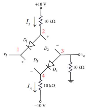
Figure 2
Apply the Kirchhoff’s voltage to the outer branch of the circuit shown in figure 2.
The voltage at node
The voltage at node
Apply the Kirchhoff’s voltage to the input branch of the circuit shown in figure 2.
Therefore,
The voltage at node
The diode
The diode
Therefore, diodes
Therefore, the output voltage is constant for
Case 3:
Assume that diodes
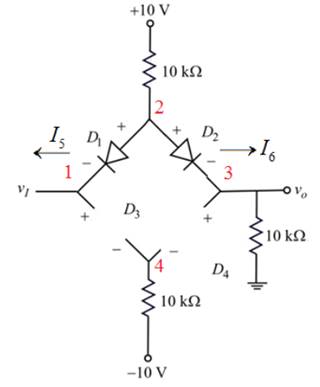
Figure 3
Apply the Kirchhoff’s current law at node
The diode
Apply the Kirchhoff’s voltage law to the input branch of the circuit shown in figure 3.
The voltage across diode
Consider equation(1).
Rewrite as,
Therefore, the output voltage is,
Therefore, plot
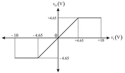
Conclusion:
Therefore, plot of
Want to see more full solutions like this?
Chapter 2 Solutions
Microelectronics: Circuit Analysis and Design


- Please can you solve this question in a step by step form correctly, please look at the refernces provided on the data path control lines, the GPLB functions, the processor instruction set and using the PLA personality chart.arrow_forwardPlease can you solve this question correctly in a step by step form to help understanding, please make it clear.arrow_forwardI just want to know what is PPE and Give examples of itarrow_forward
- Why is a starting resistor needed to bring a motor up to speed? Show one way to reverse the direction of ro- tation of a compound motor.arrow_forward8- is flip-flop which indicates some condition which arises after the execution of an arithmetic or logic instruction. a) Status flag b) Instruction registers c) Temporary register d) None of these 9- El instruction is a_ a) Branching Instructions b) Logical Instructions c) Control Instructions d) Data Transfer Instruction e) Arithmetic Instructionsarrow_forward1. Write a program to add 4 hex numbers located in the memory locations 2001h, 2002h, 2003h, 2004h and store the result at location 2005harrow_forward
- not use ai pleasearrow_forward17- In 8085 name the 16 bit registers. a) Program Counter b) Stack Pointer c) a and b d) Instruction Register 18- In response to RST 7.5 interrupt, the execution of control transfers to memory location. a) 0000H b) 003CH c) 002CH d) 0034H 19- Let contents of accumulator and B are 00000100 and 01000000 respectively. After execution of SUB B instruction, accumulator contents are a) 11000100 b) 01000000 c) 010001000 d) 00000100arrow_forward1.) A single instruction to clear the lower 4 bits of accumulator in 8085 alp is, a) XRI FOH b) XRI OFH c) ANI OFH d) ANI FO 2.) The status of Z, AC, CY flags after execution of following instructions are, MVI A, A9H MVI B, 57H ADD B HLT a) 0,1,1 b) 1,0,0 c) 1,1,1 d) 1,0,1 3.) Consider the loop: LXI H 000A MVI C OB LOOP: DCX H DCR C JNZ LOOP HLT This loop will be executed by: a) infinite times b) 11 time c) 10 times d) 1 timearrow_forward
- Fundamentals Of Energy Systems HW 6 Q6arrow_forwardFundamentals Of Energy Systems HW 6 Q4arrow_forward1. For the 2-dimensional lattice shown in the following figure, using the two sets of given primitive translation vectors to write the translation vectors that can translate lattice point A to point B. (10 pts) (1) (2) (1) T= (2) T T=arrow_forward
