
International Edition---engineering Mechanics: Statics, 4th Edition
4th Edition
ISBN: 9781305501607
Author: Andrew Pytel And Jaan Kiusalaas
Publisher: CENGAGE L
expand_more
expand_more
format_list_bulleted
Videos
Textbook Question
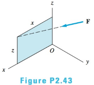
Chapter 2, Problem 2.43P
The moment of the force
Expert Solution & Answer
Want to see the full answer?
Check out a sample textbook solution
Students have asked these similar questions
Q1/ Find L[t et sin t]
Q2/ Find The Laplace Transform
f(t) = [sint
[sint 0
b) The 50 mm diameter rod is placed in a hole, lubricated walls. There is no clearance
between the rod and the sides of the hole. Determine the change in length of the rod if
an 8 kN load is applied. Take E(brass) = 80 GPa; v = 0.55
[10]
50 mmm
300 rat
3
The Mach number NM for flow of a perfect gas in a pipe depends upon the specific-heat ratio k (dimensionless), the pressure p, the density ρ, and the velocity V. Obtain by dimensional reasoning the form of the Mach number expression. (Buckingham pi)Answer: NM = f(V/sqrt(p/ρ), k)
Chapter 2 Solutions
International Edition---engineering Mechanics: Statics, 4th Edition
Ch. 2 - Â Which of the force system shown are equivalent...Ch. 2 - Two men are trying to roll the boulder by applying...Ch. 2 - The magnitudes of the three forces applied to the...Ch. 2 - Replace the three forces by a single equivalent...Ch. 2 - Replace the three forces with a single equivalent...Ch. 2 - The forces P1=110lb,P2=200lb, and P3=150lb are...Ch. 2 - Determine the magnitudes of the three forces...Ch. 2 - The magnitudes of the three forces acting on the...Ch. 2 - Determine the three forces acting on the plate...Ch. 2 - The force R is the resultant of the forces P1,P2,...
Ch. 2 - Knowing that the resultant of the two forces is...Ch. 2 - Knowing that the forces P and Q are equivalent to...Ch. 2 - Three ropes support the weight at A. The tension...Ch. 2 - Find the forces Q1,Q2, and Q3 so that the two...Ch. 2 - The man exerts a force P of magnitude 40 1b on the...Ch. 2 - The three forces acting on the beam can be...Ch. 2 - The trapdoor is held in the horizontal plane by...Ch. 2 - Replace the three forces acting on the guy wires...Ch. 2 - The horizontal boom carries the weight W=108lb at...Ch. 2 - The three forces, each of magnitude F, are applied...Ch. 2 - Determine the resultant force R that is equivalent...Ch. 2 - Determine the magnitude and sense of the moment of...Ch. 2 - Find the magnitude and sense of the moment of the...Ch. 2 - Two forces of magnitude P each act on the beam....Ch. 2 - A force P in the xy-plane acts on the triangular...Ch. 2 - A force P in the xy-plane acts on the triangular...Ch. 2 - Determine the moment of the force F=9i+18jlb about...Ch. 2 - Given that T=43kN and W=38kN, determine the...Ch. 2 - A moment of 50lbft about O is required to loosen...Ch. 2 - Determine the moment of the force F about point A...Ch. 2 - The resultant of the two forces shown has a line...Ch. 2 - The tow truck's front wheels will be lifted off...Ch. 2 - The force F acts on the gripper of the robot arm....Ch. 2 - Given that the magnitude of the moment of P about...Ch. 2 - The magnitude of the force P is 160 N. Determine...Ch. 2 - The magnitude of the force Q Determine the moments...Ch. 2 - The magnitude of the moment of force P about point...Ch. 2 - The magnitude of the force P is 50 kN. Determine...Ch. 2 - Determine the combined moment of the two forces...Ch. 2 - Find the combined moment of the forces P and Q...Ch. 2 - The wrench is used to tighten a nut on the wheel....Ch. 2 - The magnitudes of the two forces shown are P=16lb...Ch. 2 - The moment of the force F=50i100j70klb about point...Ch. 2 - Determine the magnitude of the moment of the 150-N...Ch. 2 - The combined moment of the two forces, each of...Ch. 2 - The force F=2i12j+5klb acts along the line AB....Ch. 2 - Calculate the combined moment of the three forces...Ch. 2 - Determine the moment of the force F=40i+30j+20kkN...Ch. 2 - Determine the moment of the 400-lb force about...Ch. 2 - The magnitude of the force F is 55 lb. Calculate...Ch. 2 - The force F=18i12j+10kN is applied to the gripper...Ch. 2 - The legs of the tripod have equal lengths. The...Ch. 2 - Determine the moment of the force F=40i8j+5kN...Ch. 2 - To lift the table without tilting, the combined...Ch. 2 - The combined moment of the three forces is zero...Ch. 2 - The trap door is held open by the rope AB. If the...Ch. 2 - The forces P and Q act on the handles of the...Ch. 2 - The magnitude of the force P is 360 N. Determine...Ch. 2 - The combined moment of P and the 20-lb force about...Ch. 2 - Determine the magnitude of the force F given that...Ch. 2 - The force F of magnitude 200Â NÂ isÂ...Ch. 2 - Calculate the moment of the force P about the axis...Ch. 2 - The force systems in Figs. (a) and (b) have the...Ch. 2 - The force F=F(0.6i+0.8j)kN is applied to the frame...Ch. 2 - Determine the combined moment of the four forces...Ch. 2 - The flexible shaft AB of the wrench is bent into a...Ch. 2 - The magnitude of the force F is 180 lb. Find the...Ch. 2 - Which of the systems are equivalent to the couple...Ch. 2 - Which of the systems are equivalent to the couple...Ch. 2 - If the couple applied to the steering wheel is to...Ch. 2 - Determine the magnitude of the couple shown.Ch. 2 - Determine the couple-vector that is equivalent to...Ch. 2 - Calculate the combined moment of the couple C and...Ch. 2 - Determine the couple-vector that is equivalent to...Ch. 2 - The two forces of magnitude F=30kN form a couple....Ch. 2 - The couple acts on the handles of a steering...Ch. 2 - The force system acting on the plate is equivalent...Ch. 2 - A couple of magnitude 3601b ft is applied about...Ch. 2 - The arm ABCD of the industrial robot lies in a...Ch. 2 - The figure shows one-half of a universal coupling...Ch. 2 - The steering column of the rack-and-pinion...Ch. 2 - Which of the systems are equivalent to the...Ch. 2 - A 15-lb force acts at point A on the high-pressure...Ch. 2 - The bracket, which is fastened to a wall by anchor...Ch. 2 - Replace the three forces applied to the beam by an...Ch. 2 - Replace the two forces shown by a force-couple...Ch. 2 - The figure shows a schematic of a torsion-bar...Ch. 2 - Replace the 250-N force with an equivalent...Ch. 2 - The magnitude of the force F acting at point A on...Ch. 2 - Replace the force-couple system acting on the pipe...Ch. 2 - (a) Replace the force F=2800i+1600j+3000klb acting...Ch. 2 - Determine the force-couple system, with the force...Ch. 2 - Replace the force F and the couple C with an...Ch. 2 - The moment of the force P about the axis AB is...Ch. 2 - Replace the force and the couple shown with an...Ch. 2 - The tensions in the cables supporting the pole are...Ch. 2 - The force acting at A is F=10i+20j5kkN. Knowing...Ch. 2 - The magnitude of the moment of the force P about...Ch. 2 - Calculate the couple-vector formed by the two...Ch. 2 - The magnitudes of the force P and couple C are...Ch. 2 - The resultant force of the three cable tensions...Ch. 2 - The force-couple system shown is equivalent to the...Ch. 2 - Replace the two forces shown with an equivalent...Ch. 2 - The three forces of magnitude P can be replaced by...Ch. 2 - Knowing that the two forces shown can be replaced...Ch. 2 - The trapdoor is held in the position shown by two...Ch. 2 - The force system consists of the force...Ch. 2 - The force system shown can be replaced with a...
Knowledge Booster


Learn more about
Need a deep-dive on the concept behind this application? Look no further. Learn more about this topic, mechanical-engineering and related others by exploring similar questions and additional content below.Similar questions
- oyfr 3. The figure shows a frame under the influence of an external loading made up of five forces and two moments. Use the scalar method to calculate moments. a. Write the resultant force of the external loading in Cartesian vector form. b. Determine the & direction of the resultant moment of the external loading about A. 15 cm 18 cm 2.2 N-m B 50 N 45° 10 cm 48 N.m 250 N 60 N 20 21 50 N 25 cm 100 N A 118, 27cm 5, 4:1arrow_forwardAssume the Link AO is the input and revolves 360°, determine a. the coordinates of limit positions of point B, b. the angles (AOC) corresponding to the limit positionsarrow_forwardoyfr 3. The figure shows a frame under the influence of an external loading made up of five forces and two moments. Use the scalar method to calculate moments. a. Write the resultant force of the external loading in Cartesian vector form. b. Determine the & direction of the resultant moment of the external loading about A. 15 cm 18 cm 2.2 N-m B 50 N 45° 10 cm 48 N.m 250 N 60 N 20 21 50 N 25 cm 100 N A 118, 27cm 5, 4:1arrow_forward
- The 2-mass system shown below depicts a disk which rotates about its center and has rotational moment of inertia Jo and radius r. The angular displacement of the disk is given by 0. The spring with constant k₂ is attached to the disk at a distance from the center. The mass m has linear displacement & and is subject to an external force u. When the system is at equilibrium, the spring forces due to k₁ and k₂ are zero. Neglect gravity and aerodynamic drag in this problem. You may assume the small angle approximation which implies (i) that the springs and dampers remain in their horizontal / vertical configurations and (ii) that the linear displacement d of a point on the edge of the disk can be approximated by d≈re. Ө K2 www m 4 Cz 777777 Jo Make the following assumptions when analyzing the forces and torques: тв 2 0>0, 0>0, x> > 0, >0 Derive the differential equations of motion for this dynamic system. Start by sketching LARGE and carefully drawn free-body-diagrams for the disk and the…arrow_forwardA linear system is one that satisfies the principle of superposition. In other words, if an input u₁ yields the output y₁, and an input u2 yields the output y2, the system is said to be linear if a com- bination of the inputs u = u₁ + u2 yield the sum of the outputs y = y1 + y2. Using this fact, determine the output y(t) of the following linear system: given the input: P(s) = = Y(s) U(s) = s+1 s+10 u(t) = e−2+ sin(t) =earrow_forwardThe manometer fluid in the figure given below is mercury where D = 3 in and h = 1 in. Estimate the volume flow in the tube (ft3/s) if the flowing fluid is gasoline at 20°C and 1 atm. The density of mercury and gasoline are 26.34 slug/ft3 and 1.32 slug/ft3 respectively. The gravitational force is 32.2 ft/s2.arrow_forward
- Using the Bernoulli equation to find the general solution. If an initial condition is given, find the particular solution. y' + xy = xy¯¹, y(0) = 3arrow_forwardTest for exactness. If exact, solve. If not, use an integrating factor as given or obtained by inspection or by the theorems in the text. a. 2xydx+x²dy = 0 b. (x2+y2)dx-2xydy = 0 c. 6xydx+5(y + x2)dy = 0arrow_forwardNewton's law of cooling. A thermometer, reading 5°C, is brought into a room whose temperature is 22°C. One minute later the thermometer reading is 12°C. How long does it take until the reading is practically 22°C, say, 21.9°C?arrow_forward
- Solve a. y' + 2xy = ex-x² b. y' + y sin x = ecosx, y(0) = −1 y(0) = −2.5arrow_forward= MMB 241 Tutorial 3.pdf 2/6 90% + + 5. The boat is traveling along the circular path with a speed of v = (0.0625t²) m/s, where t is in seconds. Determine the magnitude of its acceleration when t = 10 s. 40 m v = 0.0625² 6. If the motorcycle has a deceleration of at = (0.001s) m/s² and its speed at position A is 25 m/s, determine the magnitude of its acceleration when it passes point B. .A 90° 300 m n B 2arrow_forward= MMB 241 Tutorial 3.pdf 4/6 67% + 9. The car is traveling along the road with a speed of v = (2 s) m/s, where s is in meters. Determine the magnitude of its acceleration when s = 10 m. v = (2s) m/s 50 m 10. The platform is rotating about the vertical axis such that at any instant its angular position is u = (4t 3/2) rad, where t is in seconds. A ball rolls outward along the radial groove so that its position is r = (0.1+³) m, where t is in seconds. Determine the magnitudes of the velocity and acceleration of the ball when t = 1.5s.arrow_forward
arrow_back_ios
SEE MORE QUESTIONS
arrow_forward_ios
Recommended textbooks for you
 Elements Of ElectromagneticsMechanical EngineeringISBN:9780190698614Author:Sadiku, Matthew N. O.Publisher:Oxford University Press
 Mechanics of Materials (10th Edition)Mechanical EngineeringISBN:9780134319650Author:Russell C. HibbelerPublisher:PEARSON
 Thermodynamics: An Engineering ApproachMechanical EngineeringISBN:9781259822674Author:Yunus A. Cengel Dr., Michael A. BolesPublisher:McGraw-Hill Education
 Control Systems EngineeringMechanical EngineeringISBN:9781118170519Author:Norman S. NisePublisher:WILEY
 Mechanics of Materials (MindTap Course List)Mechanical EngineeringISBN:9781337093347Author:Barry J. Goodno, James M. GerePublisher:Cengage Learning
 Engineering Mechanics: StaticsMechanical EngineeringISBN:9781118807330Author:James L. Meriam, L. G. Kraige, J. N. BoltonPublisher:WILEY
Elements Of Electromagnetics
Mechanical Engineering
ISBN:9780190698614
Author:Sadiku, Matthew N. O.
Publisher:Oxford University Press
Mechanics of Materials (10th Edition)
Mechanical Engineering
ISBN:9780134319650
Author:Russell C. Hibbeler
Publisher:PEARSON
Thermodynamics: An Engineering Approach
Mechanical Engineering
ISBN:9781259822674
Author:Yunus A. Cengel Dr., Michael A. Boles
Publisher:McGraw-Hill Education
Control Systems Engineering
Mechanical Engineering
ISBN:9781118170519
Author:Norman S. Nise
Publisher:WILEY
Mechanics of Materials (MindTap Course List)
Mechanical Engineering
ISBN:9781337093347
Author:Barry J. Goodno, James M. Gere
Publisher:Cengage Learning
Engineering Mechanics: Statics
Mechanical Engineering
ISBN:9781118807330
Author:James L. Meriam, L. G. Kraige, J. N. Bolton
Publisher:WILEY
How to balance a see saw using moments example problem; Author: Engineer4Free;https://www.youtube.com/watch?v=d7tX37j-iHU;License: Standard Youtube License