
International Edition---engineering Mechanics: Statics, 4th Edition
4th Edition
ISBN: 9781305501607
Author: Andrew Pytel And Jaan Kiusalaas
Publisher: CENGAGE L
expand_more
expand_more
format_list_bulleted
Videos
Textbook Question
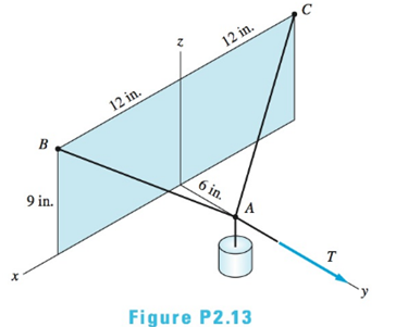
Chapter 2, Problem 2.13P
Three ropes support the weight at A. The tension in ropes AB and AC is 15 lb. Determine the tension Tin the third rope, knowing that the resultant of the three tensions is vertical.
Expert Solution & Answer

Trending nowThis is a popular solution!

Students have asked these similar questions
A hot plane surface is maintained at 100°C, and it is exposed to air at 25°C.The combined heat transfer coefficient between the surface and the air is 25W/m²·K. (same as above). In this task, you are asked to design fins to cool asurface by attaching 3 cm-long, 0.25 cm-diameter aluminum pin fins (thermalconductivity, k = 237 W/m·K) with a center-to-center distance of 0.6 cm. (Tip:do not correct the length). Determine the rate of heat transfer from thefinned structure to the air for a 1 m x 1 m section of the plate.
Heat is generated uniformly in a 4 cm-diameter, 16-cm long solid bar (k=2.4 W/m-K). The temperaturesat the center and at the surface of the bar are measured to be 210 oC and 45 oC, respectively. Calculatethe rate of heat generation within the bar. Solve the relevant energy balance equation and the boundaryconditions to calculate the rate of heat generation within the bar. (6 pts)
A hot plane surface is maintained at 100°C, and it is exposed to air at 25°C. The combined heat transfercoefficient between the surface and the air is 25 W/m²·K. You are tasked with designing an insulatingmaterial to cover the surface in order to reduce the heat transfer rate by 90%, meaning only 10% of theheat transfer would occur compared to the situation without insulation. The available insulating materialhas a thermal conductivity of 0.093 W/m·K. Assuming that the heat transfer coefficient and the surface/airtemperatures remain constant, calculate the required thickness of the insulating material in centimeters.
Chapter 2 Solutions
International Edition---engineering Mechanics: Statics, 4th Edition
Ch. 2 - Â Which of the force system shown are equivalent...Ch. 2 - Two men are trying to roll the boulder by applying...Ch. 2 - The magnitudes of the three forces applied to the...Ch. 2 - Replace the three forces by a single equivalent...Ch. 2 - Replace the three forces with a single equivalent...Ch. 2 - The forces P1=110lb,P2=200lb, and P3=150lb are...Ch. 2 - Determine the magnitudes of the three forces...Ch. 2 - The magnitudes of the three forces acting on the...Ch. 2 - Determine the three forces acting on the plate...Ch. 2 - The force R is the resultant of the forces P1,P2,...
Ch. 2 - Knowing that the resultant of the two forces is...Ch. 2 - Knowing that the forces P and Q are equivalent to...Ch. 2 - Three ropes support the weight at A. The tension...Ch. 2 - Find the forces Q1,Q2, and Q3 so that the two...Ch. 2 - The man exerts a force P of magnitude 40 1b on the...Ch. 2 - The three forces acting on the beam can be...Ch. 2 - The trapdoor is held in the horizontal plane by...Ch. 2 - Replace the three forces acting on the guy wires...Ch. 2 - The horizontal boom carries the weight W=108lb at...Ch. 2 - The three forces, each of magnitude F, are applied...Ch. 2 - Determine the resultant force R that is equivalent...Ch. 2 - Determine the magnitude and sense of the moment of...Ch. 2 - Find the magnitude and sense of the moment of the...Ch. 2 - Two forces of magnitude P each act on the beam....Ch. 2 - A force P in the xy-plane acts on the triangular...Ch. 2 - A force P in the xy-plane acts on the triangular...Ch. 2 - Determine the moment of the force F=9i+18jlb about...Ch. 2 - Given that T=43kN and W=38kN, determine the...Ch. 2 - A moment of 50lbft about O is required to loosen...Ch. 2 - Determine the moment of the force F about point A...Ch. 2 - The resultant of the two forces shown has a line...Ch. 2 - The tow truck's front wheels will be lifted off...Ch. 2 - The force F acts on the gripper of the robot arm....Ch. 2 - Given that the magnitude of the moment of P about...Ch. 2 - The magnitude of the force P is 160 N. Determine...Ch. 2 - The magnitude of the force Q Determine the moments...Ch. 2 - The magnitude of the moment of force P about point...Ch. 2 - The magnitude of the force P is 50 kN. Determine...Ch. 2 - Determine the combined moment of the two forces...Ch. 2 - Find the combined moment of the forces P and Q...Ch. 2 - The wrench is used to tighten a nut on the wheel....Ch. 2 - The magnitudes of the two forces shown are P=16lb...Ch. 2 - The moment of the force F=50i100j70klb about point...Ch. 2 - Determine the magnitude of the moment of the 150-N...Ch. 2 - The combined moment of the two forces, each of...Ch. 2 - The force F=2i12j+5klb acts along the line AB....Ch. 2 - Calculate the combined moment of the three forces...Ch. 2 - Determine the moment of the force F=40i+30j+20kkN...Ch. 2 - Determine the moment of the 400-lb force about...Ch. 2 - The magnitude of the force F is 55 lb. Calculate...Ch. 2 - The force F=18i12j+10kN is applied to the gripper...Ch. 2 - The legs of the tripod have equal lengths. The...Ch. 2 - Determine the moment of the force F=40i8j+5kN...Ch. 2 - To lift the table without tilting, the combined...Ch. 2 - The combined moment of the three forces is zero...Ch. 2 - The trap door is held open by the rope AB. If the...Ch. 2 - The forces P and Q act on the handles of the...Ch. 2 - The magnitude of the force P is 360 N. Determine...Ch. 2 - The combined moment of P and the 20-lb force about...Ch. 2 - Determine the magnitude of the force F given that...Ch. 2 - The force F of magnitude 200Â NÂ isÂ...Ch. 2 - Calculate the moment of the force P about the axis...Ch. 2 - The force systems in Figs. (a) and (b) have the...Ch. 2 - The force F=F(0.6i+0.8j)kN is applied to the frame...Ch. 2 - Determine the combined moment of the four forces...Ch. 2 - The flexible shaft AB of the wrench is bent into a...Ch. 2 - The magnitude of the force F is 180 lb. Find the...Ch. 2 - Which of the systems are equivalent to the couple...Ch. 2 - Which of the systems are equivalent to the couple...Ch. 2 - If the couple applied to the steering wheel is to...Ch. 2 - Determine the magnitude of the couple shown.Ch. 2 - Determine the couple-vector that is equivalent to...Ch. 2 - Calculate the combined moment of the couple C and...Ch. 2 - Determine the couple-vector that is equivalent to...Ch. 2 - The two forces of magnitude F=30kN form a couple....Ch. 2 - The couple acts on the handles of a steering...Ch. 2 - The force system acting on the plate is equivalent...Ch. 2 - A couple of magnitude 3601b ft is applied about...Ch. 2 - The arm ABCD of the industrial robot lies in a...Ch. 2 - The figure shows one-half of a universal coupling...Ch. 2 - The steering column of the rack-and-pinion...Ch. 2 - Which of the systems are equivalent to the...Ch. 2 - A 15-lb force acts at point A on the high-pressure...Ch. 2 - The bracket, which is fastened to a wall by anchor...Ch. 2 - Replace the three forces applied to the beam by an...Ch. 2 - Replace the two forces shown by a force-couple...Ch. 2 - The figure shows a schematic of a torsion-bar...Ch. 2 - Replace the 250-N force with an equivalent...Ch. 2 - The magnitude of the force F acting at point A on...Ch. 2 - Replace the force-couple system acting on the pipe...Ch. 2 - (a) Replace the force F=2800i+1600j+3000klb acting...Ch. 2 - Determine the force-couple system, with the force...Ch. 2 - Replace the force F and the couple C with an...Ch. 2 - The moment of the force P about the axis AB is...Ch. 2 - Replace the force and the couple shown with an...Ch. 2 - The tensions in the cables supporting the pole are...Ch. 2 - The force acting at A is F=10i+20j5kkN. Knowing...Ch. 2 - The magnitude of the moment of the force P about...Ch. 2 - Calculate the couple-vector formed by the two...Ch. 2 - The magnitudes of the force P and couple C are...Ch. 2 - The resultant force of the three cable tensions...Ch. 2 - The force-couple system shown is equivalent to the...Ch. 2 - Replace the two forces shown with an equivalent...Ch. 2 - The three forces of magnitude P can be replaced by...Ch. 2 - Knowing that the two forces shown can be replaced...Ch. 2 - The trapdoor is held in the position shown by two...Ch. 2 - The force system consists of the force...Ch. 2 - The force system shown can be replaced with a...
Knowledge Booster


Learn more about
Need a deep-dive on the concept behind this application? Look no further. Learn more about this topic, mechanical-engineering and related others by exploring similar questions and additional content below.Similar questions
- The euler parameter in the image describes the orientation of N in the reference frame of U. How do I find the euler parameters that describe the orientation of U in the reference frame of N from the given information in the image.arrow_forwardFpull Ө A person, weighing 155 lb, is being lifted by a rope thrown. over a tree branch as shown (drawing not to scale). If the static coefficient of friction between the rope and the tree branch is us = 0.67, and the 0 = 45°. Determine the pulling force required to start lifting the person and the pulling force required to keep the person from falling? Pulling force to lift the person: Pulling force to keep the person from falling: lb lbarrow_forwardThe car weighs 1630 lbs and drives up the hill at a constant speed. Assuming the static friction coefficient between the wheels and the road is μs = 0.64, determine the steepest angle that the car can climb without slipping if it is.... a.) rear wheel drive b.) front wheel drive c.) four wheel drive a C CC ①⑧ BY NC Dr. Jacob Moore Values for dimensions on the figure are given in the following table. Note the figure may not be to scale. Variable Value a 8.75 ft b 3.325 ft C 1.66 ft a.) The steepest angle for rear wheel drive is 0 max degrees. b.) The steepest angle for front wheel drive is Omax degrees. c.) The steepest angle for four wheel drive is Omax degrees. = = =arrow_forward
- For the structure below, each member of the truss will safely support a tensile force of 3 kN and a compressive force of 1 kN. Determine the largest mass m that can be safely suspended. Hint: First work through this algebraically to find the forces in each member terms of the mass "m" to determine the largest stress member. 1 m t 1 m 1 m 1m + 1m E B 1977 marrow_forwardBlock A has a mass of 34 kg and block B has a mass of 41 kg. The two blocks are stacked on the ramp with an incline of Ꮎ 0 = 15.4°. Determine the largest horizontal force F that can be applied to block B without either block moving for each of the following two cases: a.) The friction coefficient for the contact between blocks A and B is μs1 0.56 and the friction coefficient for the = contact between block A and the ramp is μs2 = 0.34. b.) The friction coefficient for the contact between blocks A and B is 1 = 0.56 and the friction coefficient for the contact between block A and the ramp is μs2 = 0.17. Ꮎ F B A Part a) The limiting slip condition occurs at Select an answer CC BY NC SA 2016 Eric Davishahl The maximum force before either block A or B slips is N Part b) The limiting slip condition occurs at Select an answer The maximum force before either block A or B slips is Narrow_forwardThe crane truck has a weight of 11000 lb and a center of gravity at point . The parking brake only locks the rear wheels of the truck, so the front wheels are free to rotate. Determine the maximum force F applied at the angle = 0 30.5° that can be exerted on the crane without it slipping or tipping for each of the following cases: Case 1: The static friction coefficient between the rear tires and the ground is μ. = 0.050. ა Case 2: The static friction coefficient between the rear tires and the ground is μα == 0.33. d CGD 口 BY NC SA F 2013 Michael Swanbom кажо с Values for dimensions on the figure are given in the following table. Note the figure may not be to scale. Variable Value a 5.5 ft b 9 ft C 4 ft 3 ft 10 ft d h For Case 1, the constraint is Select an answer F = lbs. шал For Case 2, the constraint is Select an answer F пал lbs. and andarrow_forward
- You are leaning your 5.0 ft, 15.0 lb ladder against the wall in your garage. There are 2 rubber foot paddles on the bottom of the ladder, and your garage floor is concrete. The static friction between the rubber and concrete is μs = 0.580. What is the maximum distance from the wall to the rubber foot paddles, which you can lean your ladder without it slipping? Assume the wall is smooth. S The maximum distance = ftarrow_forwardInstructions. "I have written solutions in text form, but I need experts to rewrite them in handwriting from A to Z, exactly as I have written, without any changes."arrow_forwardPearson eText Study Area mylabmastering.pearson.com Access Pearson P Pearson MyLab and Mastering Problem 14.78 P Course Home b Answered: HW_02.pdf EE 213-01 > Assignments HW_#... 2 of 8 Document Sharing User Settings The spring has a stiffness k = 200 N/m and an unstretched length of 0.5 m. It is attached to the 4.6-kg smooth collar and the collar is released from rest at A. Neglect the size of the collar. (Figure 1) Part A Determine the speed of the collar when it reaches B. Express your answer to three significant figures and include the appropriate units. Figure 1 of 1 με VB = Value Units Submit Request Answer Provide Feedback ? Review Next >arrow_forward
- Pearson eText Study Area Access Pearson mylabmastering.pearson.com P Pearson MyLab and Mastering Problem 15.79 P Course Home b Answered: HW_02.pdf EE 213-01 > Assignments HW_#... 6 of 8 > Document Sharing User Settings The two disks A and B have a mass of 4 kg and 5 kg, respectively. They collide with the initial velocities shown. The coefficient of restitution is e = 0.65. Suppose that (VA)1 = 6 m/s, (VB)1 = 8 m/s. (Figure 1) Part A Determine the magnitude of the velocity of A just after impact. Express your answer to three significant figures and include the appropriate units. Figure 1 of 1 μÅ (VA)2 = Value Units Submit Request Answer Part B ? Review Determine the angle between the x axis and the velocity of A just after impact, measured clockwise from the negative x axis. Express your answer in degrees to three significant figures. ΕΠΙ ΑΣΦ vec 01 Submit Request Answer Part C ? Determine the magnitude of the velocity of B just after impact. Express your answer to three significant…arrow_forwardPearson eText Study Area mylabmastering.pearson.com Access Pearson P Pearson MyLab and Mastering Problem 14.78 P Course Home b Answered: HW_02.pdf EE 213-01 > Assignments HW_#... 2 of 8 Document Sharing User Settings The spring has a stiffness k = 200 N/m and an unstretched length of 0.5 m. It is attached to the 4.6-kg smooth collar and the collar is released from rest at A. Neglect the size of the collar. (Figure 1) Part A Determine the speed of the collar when it reaches B. Express your answer to three significant figures and include the appropriate units. Figure 1 of 1 με VB = Value Units Submit Request Answer Provide Feedback ? Review Next >arrow_forwardPearson eText Study Area Document Sharing User Settings mylabmastering.pearson.com Access Pearson P Pearson MyLab and Mastering Problem 15.96 Part A In (Figure 1), take m₁ = 3.4 kg and m = 4.8 kg. Figure 1 of 1 P Course Home b Answered: HW_02.pdf EE 213-01 > Assignments HW_#... 7 of 8 Determine the component of the angular momentum Ho of particle A about point O. Express your answer in kilogram-meters squared per second to three significant figures. (Ho) z = -ΜΕ ΑΣΦ vec Submit Request Answer Part B ? kg m2/s Determine the component of the angular momentum Ho of particle B about point O. Suppose that Express your answer in kilogram-meters squared per second to three significant figures. ΜΕ ΑΣΦ vec Symbols (Ho)z = Submit Request Answer Provide Feedback ? kg m2/s Review Next >arrow_forward
arrow_back_ios
SEE MORE QUESTIONS
arrow_forward_ios
Recommended textbooks for you
 International Edition---engineering Mechanics: St...Mechanical EngineeringISBN:9781305501607Author:Andrew Pytel And Jaan KiusalaasPublisher:CENGAGE L
International Edition---engineering Mechanics: St...
Mechanical Engineering
ISBN:9781305501607
Author:Andrew Pytel And Jaan Kiusalaas
Publisher:CENGAGE L
How to balance a see saw using moments example problem; Author: Engineer4Free;https://www.youtube.com/watch?v=d7tX37j-iHU;License: Standard Youtube License