International Edition---engineering Mechanics: Statics, 4th Edition
4th Edition
ISBN: 9781305501607
Author: Andrew Pytel And Jaan Kiusalaas
Publisher: CENGAGE L
expand_more
expand_more
format_list_bulleted
Textbook Question
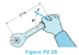
Chapter 2, Problem 2.29P
A moment of

Expert Solution & Answer
Trending nowThis is a popular solution!

Students have asked these similar questions
Plot the displacement diagram for a cam with roller follower of diameter 10 mm. The required
motion is as follows;
1- Rising 60 mm in 135° with uniform acceleration and retardation motion.
2- Dwell 90°
3- Falling 60 mm for 135° with Uniform acceleration-retardation motion.
Then design the cam profile to give the above displacement diagram if the minimum circle
diameter of the cam is 50 mm.
Q1/ A vertical, circular gate with water on one side as shown. Determine
the total resultant force acting on the gate and the location of the center of
pressure, use water specific weight 9.81 kN/m³
1 m
4 m
I need handwritten solution with sketches for each
Chapter 2 Solutions
International Edition---engineering Mechanics: Statics, 4th Edition
Ch. 2 - Â Which of the force system shown are equivalent...Ch. 2 - Two men are trying to roll the boulder by applying...Ch. 2 - The magnitudes of the three forces applied to the...Ch. 2 - Replace the three forces by a single equivalent...Ch. 2 - Replace the three forces with a single equivalent...Ch. 2 - The forces P1=110lb,P2=200lb, and P3=150lb are...Ch. 2 - Determine the magnitudes of the three forces...Ch. 2 - The magnitudes of the three forces acting on the...Ch. 2 - Determine the three forces acting on the plate...Ch. 2 - The force R is the resultant of the forces P1,P2,...
Ch. 2 - Knowing that the resultant of the two forces is...Ch. 2 - Knowing that the forces P and Q are equivalent to...Ch. 2 - Three ropes support the weight at A. The tension...Ch. 2 - Find the forces Q1,Q2, and Q3 so that the two...Ch. 2 - The man exerts a force P of magnitude 40 1b on the...Ch. 2 - The three forces acting on the beam can be...Ch. 2 - The trapdoor is held in the horizontal plane by...Ch. 2 - Replace the three forces acting on the guy wires...Ch. 2 - The horizontal boom carries the weight W=108lb at...Ch. 2 - The three forces, each of magnitude F, are applied...Ch. 2 - Determine the resultant force R that is equivalent...Ch. 2 - Determine the magnitude and sense of the moment of...Ch. 2 - Find the magnitude and sense of the moment of the...Ch. 2 - Two forces of magnitude P each act on the beam....Ch. 2 - A force P in the xy-plane acts on the triangular...Ch. 2 - A force P in the xy-plane acts on the triangular...Ch. 2 - Determine the moment of the force F=9i+18jlb about...Ch. 2 - Given that T=43kN and W=38kN, determine the...Ch. 2 - A moment of 50lbft about O is required to loosen...Ch. 2 - Determine the moment of the force F about point A...Ch. 2 - The resultant of the two forces shown has a line...Ch. 2 - The tow truck's front wheels will be lifted off...Ch. 2 - The force F acts on the gripper of the robot arm....Ch. 2 - Given that the magnitude of the moment of P about...Ch. 2 - The magnitude of the force P is 160 N. Determine...Ch. 2 - The magnitude of the force Q Determine the moments...Ch. 2 - The magnitude of the moment of force P about point...Ch. 2 - The magnitude of the force P is 50 kN. Determine...Ch. 2 - Determine the combined moment of the two forces...Ch. 2 - Find the combined moment of the forces P and Q...Ch. 2 - The wrench is used to tighten a nut on the wheel....Ch. 2 - The magnitudes of the two forces shown are P=16lb...Ch. 2 - The moment of the force F=50i100j70klb about point...Ch. 2 - Determine the magnitude of the moment of the 150-N...Ch. 2 - The combined moment of the two forces, each of...Ch. 2 - The force F=2i12j+5klb acts along the line AB....Ch. 2 - Calculate the combined moment of the three forces...Ch. 2 - Determine the moment of the force F=40i+30j+20kkN...Ch. 2 - Determine the moment of the 400-lb force about...Ch. 2 - The magnitude of the force F is 55 lb. Calculate...Ch. 2 - The force F=18i12j+10kN is applied to the gripper...Ch. 2 - The legs of the tripod have equal lengths. The...Ch. 2 - Determine the moment of the force F=40i8j+5kN...Ch. 2 - To lift the table without tilting, the combined...Ch. 2 - The combined moment of the three forces is zero...Ch. 2 - The trap door is held open by the rope AB. If the...Ch. 2 - The forces P and Q act on the handles of the...Ch. 2 - The magnitude of the force P is 360 N. Determine...Ch. 2 - The combined moment of P and the 20-lb force about...Ch. 2 - Determine the magnitude of the force F given that...Ch. 2 - The force F of magnitude 200Â NÂ isÂ...Ch. 2 - Calculate the moment of the force P about the axis...Ch. 2 - The force systems in Figs. (a) and (b) have the...Ch. 2 - The force F=F(0.6i+0.8j)kN is applied to the frame...Ch. 2 - Determine the combined moment of the four forces...Ch. 2 - The flexible shaft AB of the wrench is bent into a...Ch. 2 - The magnitude of the force F is 180 lb. Find the...Ch. 2 - Which of the systems are equivalent to the couple...Ch. 2 - Which of the systems are equivalent to the couple...Ch. 2 - If the couple applied to the steering wheel is to...Ch. 2 - Determine the magnitude of the couple shown.Ch. 2 - Determine the couple-vector that is equivalent to...Ch. 2 - Calculate the combined moment of the couple C and...Ch. 2 - Determine the couple-vector that is equivalent to...Ch. 2 - The two forces of magnitude F=30kN form a couple....Ch. 2 - The couple acts on the handles of a steering...Ch. 2 - The force system acting on the plate is equivalent...Ch. 2 - A couple of magnitude 3601b ft is applied about...Ch. 2 - The arm ABCD of the industrial robot lies in a...Ch. 2 - The figure shows one-half of a universal coupling...Ch. 2 - The steering column of the rack-and-pinion...Ch. 2 - Which of the systems are equivalent to the...Ch. 2 - A 15-lb force acts at point A on the high-pressure...Ch. 2 - The bracket, which is fastened to a wall by anchor...Ch. 2 - Replace the three forces applied to the beam by an...Ch. 2 - Replace the two forces shown by a force-couple...Ch. 2 - The figure shows a schematic of a torsion-bar...Ch. 2 - Replace the 250-N force with an equivalent...Ch. 2 - The magnitude of the force F acting at point A on...Ch. 2 - Replace the force-couple system acting on the pipe...Ch. 2 - (a) Replace the force F=2800i+1600j+3000klb acting...Ch. 2 - Determine the force-couple system, with the force...Ch. 2 - Replace the force F and the couple C with an...Ch. 2 - The moment of the force P about the axis AB is...Ch. 2 - Replace the force and the couple shown with an...Ch. 2 - The tensions in the cables supporting the pole are...Ch. 2 - The force acting at A is F=10i+20j5kkN. Knowing...Ch. 2 - The magnitude of the moment of the force P about...Ch. 2 - Calculate the couple-vector formed by the two...Ch. 2 - The magnitudes of the force P and couple C are...Ch. 2 - The resultant force of the three cable tensions...Ch. 2 - The force-couple system shown is equivalent to the...Ch. 2 - Replace the two forces shown with an equivalent...Ch. 2 - The three forces of magnitude P can be replaced by...Ch. 2 - Knowing that the two forces shown can be replaced...Ch. 2 - The trapdoor is held in the position shown by two...Ch. 2 - The force system consists of the force...Ch. 2 - The force system shown can be replaced with a...
Knowledge Booster
Learn more about
Need a deep-dive on the concept behind this application? Look no further. Learn more about this topic, mechanical-engineering and related others by exploring similar questions and additional content below.Similar questions
- Given answers to be: i) 14.65 kN; 6.16 kN; 8.46 kN ii) 8.63 kN; 9.88 kN iii) Bearing 6315 for B1 & B2, or Bearing 6215 for B1arrow_forward(b) A steel 'hot rolled structural hollow section' column of length 5.75 m, has the cross-section shown in Figure Q.5(b) and supports a load of 750 kN. During service, it is subjected to axial compression loading where one end of the column is effectively restrained in position and direction (fixed) and the other is effectively held in position but not in direction (pinned). i) Given that the steel has a design strength of 275 MN/m², determine the load factor for the structural member based upon the BS5950 design approach using Datasheet Q.5(b). [11] ii) Determine the axial load that can be supported by the column using the Rankine-Gordon formula, given that the yield strength of the material is 280 MN/m² and the constant *a* is 1/30000. [6] 300 600 2-300 mm wide x 5 mm thick plates. Figure Q.5(b) L=5.75m Pinned Fixedarrow_forwardHelp ارجو مساعدتي في حل هذا السؤالarrow_forward
- Q10) Body A weighs 600 lb contact with smooth surfaces at D and E. Determine the tension in the cord and the forces acting on C on member BD, also calculate the reaction at B and F. Cable 6' 3' wwwarrow_forwardHelp ارجو مساعدتي في حل هذا السؤالarrow_forwardQ3: Find the resultant of the force system.arrow_forward
- Question 1 A three-blade propeller of a diameter of 2 m has an activity factor AF of 200 and its ratio of static thrust coefficient to static torque coefficient is 10. The propeller's integrated lift coefficient is 0.3.arrow_forward(L=6847 mm, q = 5331 N/mm, M = 1408549 N.mm, and El = 8.6 x 10¹⁴ N. mm²) X A ΕΙ B L Y Marrow_forwardCalculate the maximum shear stress Tmax at the selected element within the wall (Fig. Q3) if T = 26.7 KN.m, P = 23.6 MPa, t = 2.2 mm, R = 2 m. The following choices are provided in units of MPa and rounded to three decimal places. Select one: ○ 1.2681.818 O 2. 25745.455 O 3. 17163.636 O 4. 10727.273 ○ 5.5363.636arrow_forward
arrow_back_ios
SEE MORE QUESTIONS
arrow_forward_ios
Recommended textbooks for you
 International Edition---engineering Mechanics: St...Mechanical EngineeringISBN:9781305501607Author:Andrew Pytel And Jaan KiusalaasPublisher:CENGAGE L

International Edition---engineering Mechanics: St...
Mechanical Engineering
ISBN:9781305501607
Author:Andrew Pytel And Jaan Kiusalaas
Publisher:CENGAGE L
How to balance a see saw using moments example problem; Author: Engineer4Free;https://www.youtube.com/watch?v=d7tX37j-iHU;License: Standard Youtube License