
Concept explainers
Videos
Using the y parameters, derive formulas for Zin, Zout, Ai, and Av for the common-emitter transistor circuit.
Derive the formulae for input impedance, output impedance, current gain, and voltage gain for the common-emitter transistor circuit using y parameters.
Explanation of Solution
Formula used:
Write the expressions for admittance parameters of a two-port network as follows:
Refer to Figure 19.56 (a) for schematic circuit of common-emitter amplifier (transistor) and write the formulae for input impedance, output impedance, current gain, and voltage gain for the common-emitter transistor circuit as follows:
Write the expression for voltage gain of a common-emitter transistor as follows:
Here,
Write the expression for current gain of a common-emitter transistor as follows:
Here,
Write the expression for input impedance of a common-emitter transistor follows:
Write the expression for output impedance of a common-emitter transistor as follows:
Calculation:
Draw a two-port circuit to obtain input impedance, current gain, and voltage gain for the common-emitter transistor circuit as shown in Figure 1.
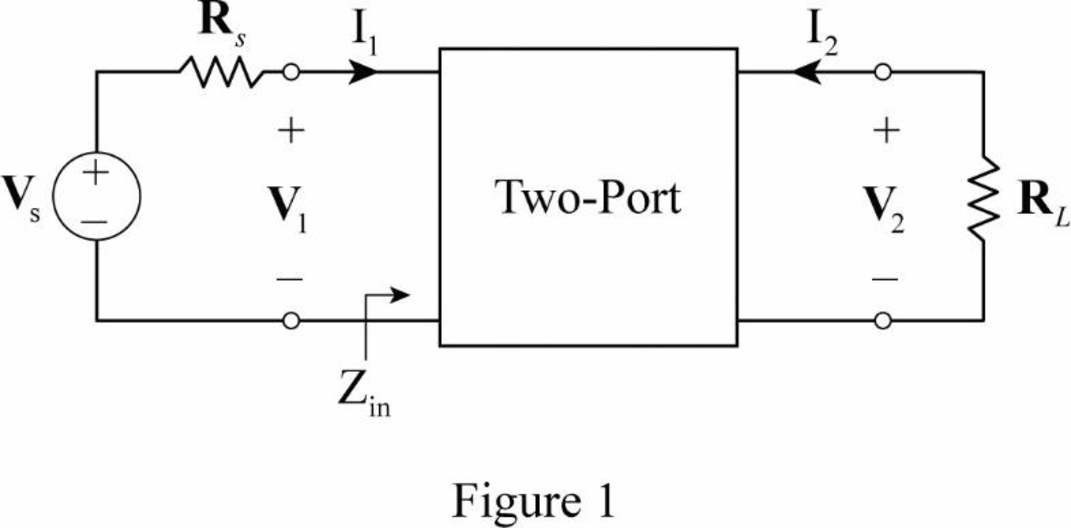
From Figure 1, write the expression for current
Substitute
Substitute
Consider
As the
Rearrange the expression as follows:
Substitute
As the current
Modify the expression in Equation (7) for common-emitter transistor circuit as follows:
Substitute
Substitute
From Equation (8), substitute
Substitute
Draw a two-port circuit to obtain output impedance for the common-emitter transistor circuit as shown in Figure 2.
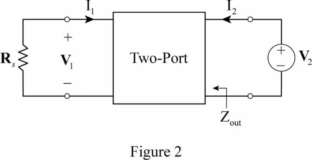
From Figure 2, write the expression for output impedance as follows:
From Equation (2), substitute
From Figure 2, write the expression for
Substitute
Substitute
From the calculations, the formulae for input impedance, output impedance, current gain, and voltage gain for the common-emitter transistor circuit are derived as follows:
Conclusion:
Thus, the formulae for input impedance, output impedance, current gain, and voltage gain for the common-emitter transistor circuit are derived.
Want to see more full solutions like this?
Chapter 19 Solutions
Fundamentals of Electric Circuits


- NO AI PLEASE.arrow_forward2-3) For each of the two periodic signals in the figures below, find the exponential Fourier series and sketch the magnitude and angle spectra. -5 ΟΙ 1 1- (a) (b) -20π -10x -π Π 10m 20m 1-arrow_forwardI need help with this problem and an explanation of the solution for the image described below. (Introduction to Signals and Systems)arrow_forward
- In the op-amp circuit shown in Fig. P8.32,uin(t) = 12cos(1000t) V,R = 10 k Ohm , RL = 5 k Ohm, and C = 1 μF. Determine the complexpower for each of the passive elements in the circuit. Isconservation of energy satisfied?arrow_forward2-4) Similar to Lathi & Ding prob. 2.9-4 (a) For signal g(t)=t, find the exponential Fourier series to represent g(t) over the interval(0, 1). (b) Sketch the original signal g(t) and the everlasting signal g'(t) represented by the same Fourier series. (c) Verify Parseval's theorem [eq. (2.103b)] for g'(t), given that: = n 1 6arrow_forward8.24 In the circuit of Fig. P8.24, is(t) = 0.2sin105t A,R = 20 W, L = 0.1 mH, and C = 2 μF. Show that the sum ofthe complex powers for the three passive elements is equal to thecomplex power of the source.arrow_forward
 Introductory Circuit Analysis (13th Edition)Electrical EngineeringISBN:9780133923605Author:Robert L. BoylestadPublisher:PEARSON
 Delmar's Standard Textbook Of ElectricityElectrical EngineeringISBN:9781337900348Author:Stephen L. HermanPublisher:Cengage Learning
 Programmable Logic ControllersElectrical EngineeringISBN:9780073373843Author:Frank D. PetruzellaPublisher:McGraw-Hill Education
 Fundamentals of Electric CircuitsElectrical EngineeringISBN:9780078028229Author:Charles K Alexander, Matthew SadikuPublisher:McGraw-Hill Education
 Electric Circuits. (11th Edition)Electrical EngineeringISBN:9780134746968Author:James W. Nilsson, Susan RiedelPublisher:PEARSON
 Engineering ElectromagneticsElectrical EngineeringISBN:9780078028151Author:Hayt, William H. (william Hart), Jr, BUCK, John A.Publisher:Mcgraw-hill Education,