
Calculate the voltage gain, current gain, input impedance, and output impedance for the transistor network shown in Figure 19.132 in the textbook.
Answer to Problem 93P
The voltage gain, current gain, input impedance, and output impedance for the transistor network are
Explanation of Solution
Given Data:
Refer to Figure 19.132 in the textbook for the transistor network circuit.
From the given transistor network circuit, the internal resistance
Formula used:
Refer to Equation 19.73 in the textbook and write the expression for voltage gain of a transistor network in terms of hybrid parameters as follows:
Here,
Write the expression for current gain of the transistor network as follows:
Here,
Write the expression for input impedance of the transistor network as follows:
Calculation:
Redraw the given circuit as shown in Figure 1.
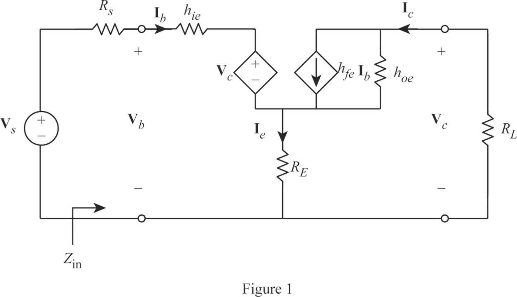
From Figure 1, write the expression for emitter current as follows:
Write the expression for base voltage from the circuit in Figure 1 as follows:
Write the expression for collector current as follows:
Write the expression for collector voltage as follows:
From Equation (7), substitute
Rearrange the expression as follows:
From Equation (2), substitute
Substitute 150 for
From Equation (6), substitute
Rearrange the expression as follows:
Rearrange the expression in Equation (5) as follows:
From Equations (7) and (9), substitute
Rearrange the expression as follows:
Substitute 150 for
Simplify the expression as follows:
From Equation (1), substitute
From Equation (9), substitute
Rearrange the expression as follows:
Substitute 150 for
From Equation (3), substitute
Consider output voltage
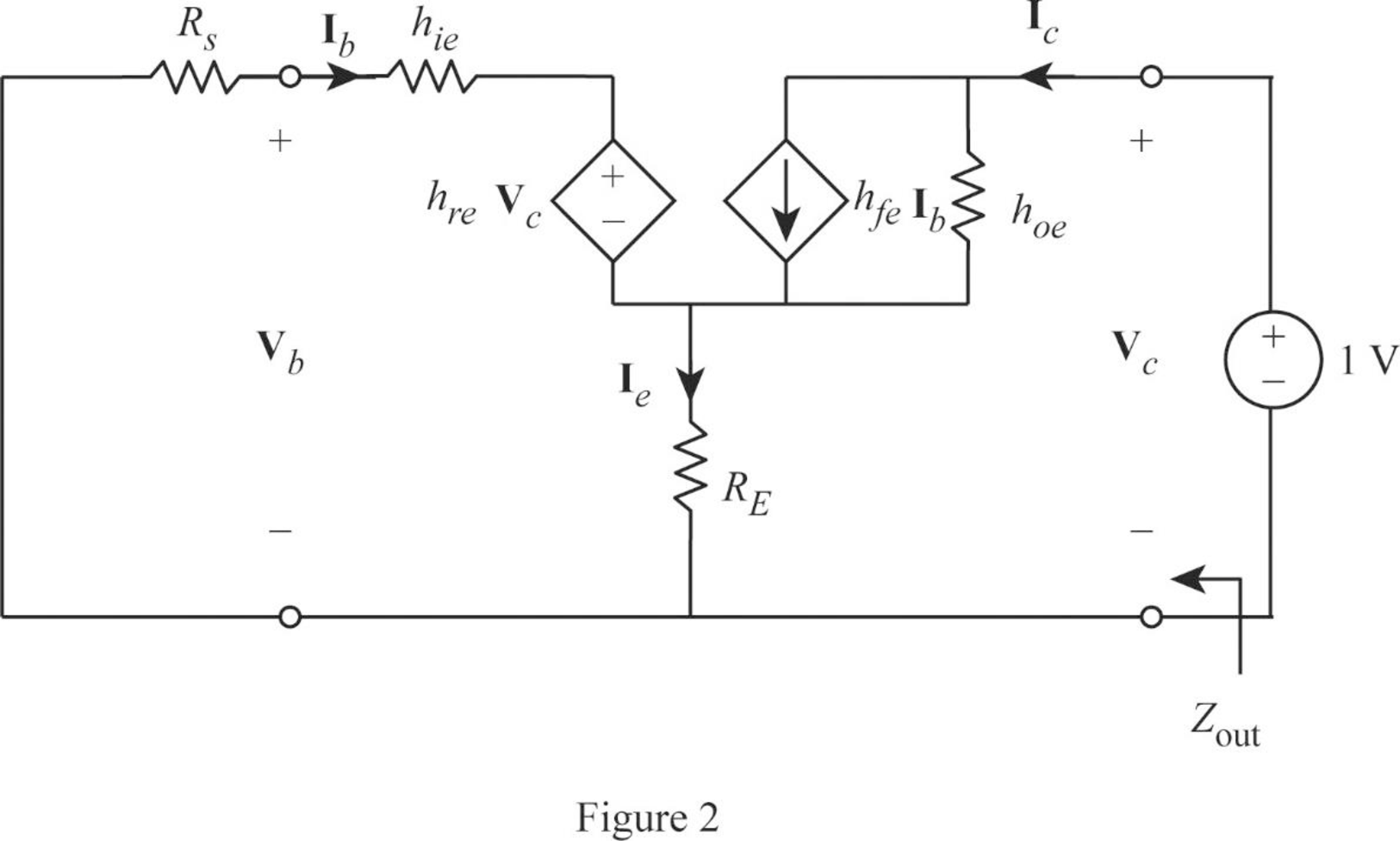
Apply KVL to the input loop for the circuit in Figure 2 as follows:
Substitute 1 for
Apply KCL at the output node for the circuit in Figure 2 as follows:
Substitute 1 for
Rearrange the expression as follows:
From Equation (12), substitute
Substitute 150 for
Write the expression for output impedance of the transistor network as follows:
Substitute 1 for
Conclusion:
Thus, the voltage gain, current gain, input impedance, and output impedance for the transistor network are
Want to see more full solutions like this?
Chapter 19 Solutions
Fundamentals of Electric Circuits

- 12.4 Determine the Laplace transform of each of the followingfunctions by applying the properties given in the Tables (a) f1(t) = 4te−2t u(t)(b) f2(t) = 10cos(12t +60◦) u(t)*(c) f3(t) = 12e−3(t−4) u(t −4)(d) f4(t) = 30(e−3t +e3t ) u(t)(e) f5(t) = 16e−2t cos4t u(t)(f) f6(t) = 20te−2t sin4t u(t)arrow_forward8. Obtain the inverse Laplace transform of each of the followingfunctions by first applying the partial-fraction-expansionmethod.(a) F1(s) =6(s+2)(s+4)(b) F2(s) =4(s+1)(s+2)2(c) F3(s) =3s3 +36s2 +131s+144s(s+4)(s2 +6s+9)(d) F4(s) =2s2 +4s−10(s+6)(s+2)2arrow_forward12.12 In the circuit of Fig. P12.12(a), is(t) is given by the waveform shown in Fig. P12.12(b). Determine iL (t) for t≥ 0, given that R₁ = R₂ = 2 2 and L = 4 H. is() R₁ R2: (a) Circuit is(t) 8A- 8e-21 elle (b) is(t) Figure P12.12 Circuit and waveform for Problem 12.12. iLarrow_forward
- 12.12 In the circuit of Fig. P12.12(a), is(t) is given by thewaveform shown in Fig. P12.12(b). Determine iL(t) for t ≥ 0,given that R1 = R2 = 2 W and L = 4 H.arrow_forward12.4 Determine the Laplace transform of each of the following functions by applying the properties given in Tables 12-1 and 12-2 on pages 642-643. (a) fi(t)=4tet u(t) (b) f2(t)=10cos (12t+60°) u(t) *(c) f3(t) = 12e−3(t−4) u(t −4) (d) f4(t) = 30(e³ +e³t) u(t) (e) fs(t)=16e2t cos 4t u(t) (f) f6(t)=20te 2 sin 4t u(t)arrow_forwarda) Calculate the values of v and i. + 803 1A Va 82 b) Determine the power dissipated in each resistor. 1A Va (a) + I 50 V 0.2 S (b) + D + 1 Α υ€ 20 Ω 50 V 250 ΩΣ ia (c) (d) Copyright ©2015 Pearson Education, All Rights Reservedarrow_forward
- Exercise 3-12: Find the Thévenin equivalent of the circuit to the left of terminals (a, b) in Fig. E3.12, and then determine the current I. 502 502 0.6 Ω 20 V | + <302 Ω ΣΙΩ b 2025 Ω 15A Figure E3.12arrow_forward2. Consider following feedback system. r(t) e(t) y(t) K G(s) 1 where G(S) = s²+as+b In above, K, a and b are constants. Select the values of K, a and b in a way so that (i) (ii) (iii) the closed loop system is stable, steady-state error of the closed-loop system for step input is 0.2, the closed-loop response has 20% overshoot and 2 seconds as settling time.arrow_forward4. Answer the following questions. Take help from ChatGPT to answer these questions (if you need). But write the answers briefly using your own words with no more than two sentences, and make sure you check whether ChatGPT is giving you the appropriate answers in the context of class. a) What is the advantage of the PI controller over the proportional controller? b) What is the advantage of the PD controller over a proportional controller? c) In the presence of noise, what problem do we face implementing the derivate part of the PID (or PD) controller? To address this, what do we usually use? d) What are the forms of lead compensator and lag compensator? How do these two types of compensators differ?arrow_forward
- 3. Consider the following closed-loop system as shown in the figure. 16 Ge(s) s(s + 4) Suppose Ge(s) is a PID controller with Kp = 1, KD = 2 and K₁ = 3. a) Find the controller transfer function G₁(s). b) Find the open-loop transfer function. c) Find the closed-loop transfer function.arrow_forwardExercise 3-12: Find the Thévenin equivalent of the circuit to the left of terminals (a, b) in Fig. E3.12, and then determine the current I. 502 5 Ω 0.6 Ω a 3Ω ΣΙΩ b 20 V 1 + 2027 15A Figure E3.12arrow_forwardsolve and show workarrow_forward
 Introductory Circuit Analysis (13th Edition)Electrical EngineeringISBN:9780133923605Author:Robert L. BoylestadPublisher:PEARSON
 Delmar's Standard Textbook Of ElectricityElectrical EngineeringISBN:9781337900348Author:Stephen L. HermanPublisher:Cengage Learning
 Programmable Logic ControllersElectrical EngineeringISBN:9780073373843Author:Frank D. PetruzellaPublisher:McGraw-Hill Education
 Fundamentals of Electric CircuitsElectrical EngineeringISBN:9780078028229Author:Charles K Alexander, Matthew SadikuPublisher:McGraw-Hill Education
 Electric Circuits. (11th Edition)Electrical EngineeringISBN:9780134746968Author:James W. Nilsson, Susan RiedelPublisher:PEARSON
 Engineering ElectromagneticsElectrical EngineeringISBN:9780078028151Author:Hayt, William H. (william Hart), Jr, BUCK, John A.Publisher:Mcgraw-hill Education,