
Concept explainers
Videos
The circuit in Fig. 19.116 may be regarded as two two-ports connected in parallel. Obtain the y parameters as functions of s.
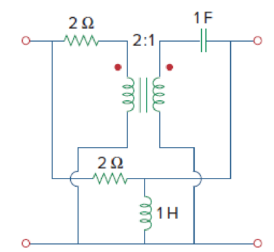
Figure 19.116
Find the admittance parameters for the given two-port network in Figure 19.116 in the textbook.
Answer to Problem 69P
The admittance parameters for the given two-port network are
Explanation of Solution
Given Data:
Refer to Figure 19.116 in the textbook for the given two-port network.
Formula used:
Write the expressions for admittance parameters of a two-port network as follows:
Calculation:
Note that the dimensions are neglected for simple calculations.
Consider upper network as network
As the interconnection network is a parallel combination of two networks, it is easier to obtain the required objective in terms of admittance parameters. Find the admittance parameters for upper and lower network and add them to obtain the overall admittance parameters.
The admittance parameters
Redraw the upper network by short circuiting the port-2 as shown in Figure 1.
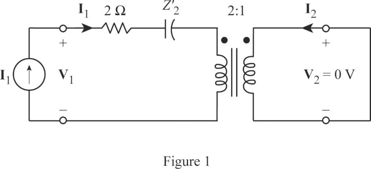
Write the expression for equivalent impedance of secondary winding capacitance when the transformer is referred to the primary winding as follows:
Here,
Substitute
From Figure 1, write the expression for
Substitute
Rearrange the expression as follows:
Substitute
From Figure 1, write the expression for
From Equation (6), substitute
Rearrange the expression as follows:
Substitute
The admittance parameters
Redraw the given two-port network by short circuiting the port-1 as shown in Figure 2.
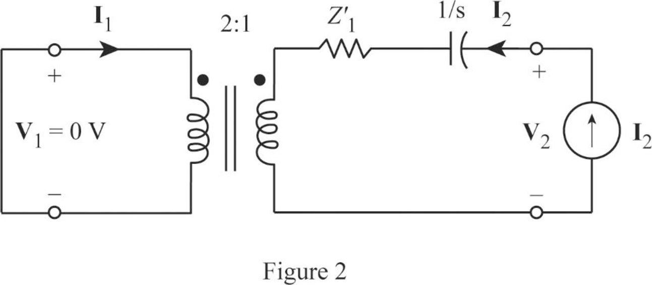
Write the expression for equivalent impedance of primary winding resistance when the transformer is referred to the secondary winding as follows:
Here,
Substitute
From Figure2, write the expression for
Substitute 0.5 for
Rearrange the expression as follows:
Substitute
From Figure 1, write the expression for
From Equation (10), substitute
Rearrange the expression as follows:
Substitute
From the calculations, write the y-parameters for upper network as follows:
Redraw the lower network by short circuiting the port-2 as shown in Figure 3.
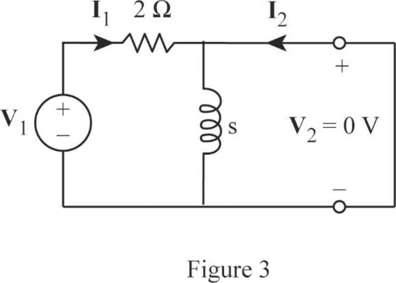
As the current bypasses through the short circuit path, redraw the circuit in Figure 3 as shown in Figure 4.
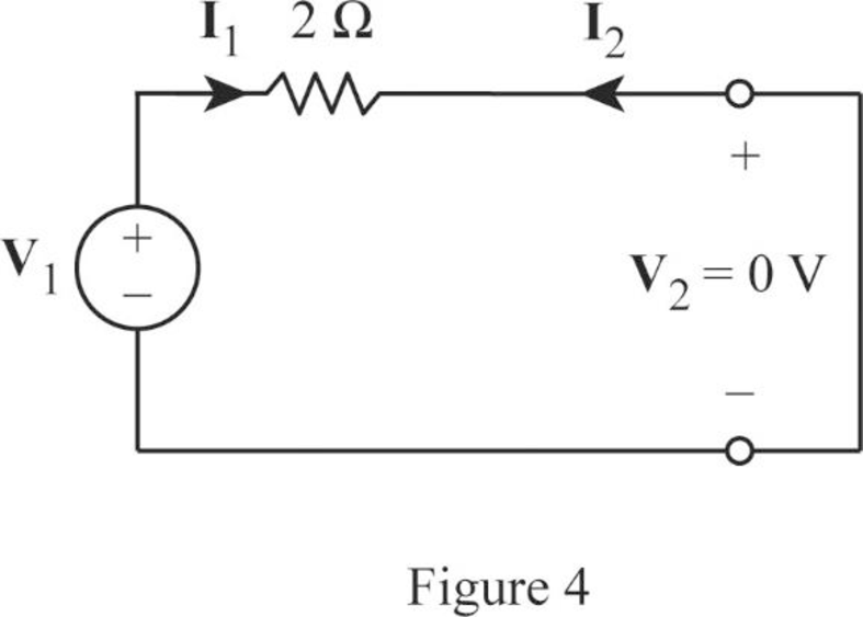
From Figure 4, write the expression for
Rearrange the expression as follows:
Substitute 0.5 for
From Figure 1, the expression for current
From Equation (11), substitute
Rearrange the expression as follows:
Substitute
Redraw the lower network by short circuiting the port-1 as shown in Figure 5.
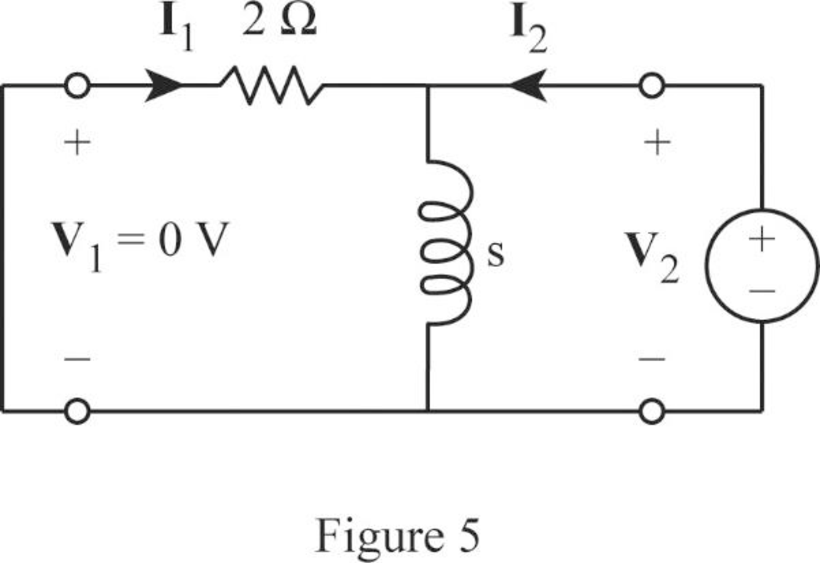
From Figure 5, write the expression for
Rearrange the expression as follows:
Substitute
From Figure 5, obtain the current
From Equation (12), substitute
Rearrange the expression as follows:
Substitute
From the calculations, write the y-parameters for lower network as follows:
As the upper and lower networks are connected in parallel, write the expression for overall admittance parameters as follows:
Substitute
Simplify the expression as follows:
Conclusion:
Thus, the admittance parameters for the given two-port network are
Want to see more full solutions like this?
Chapter 19 Solutions
Fundamentals of Electric Circuits


- A lighting load of 600 kW and a motor load of 707 kW at 0.707 p.f lagging are supplied by two alternators running in parallel. One machine supplies 900 kW at 0.9 p.f lagging. Find the load sharing and p.f of second machine?arrow_forwardPlease draw out the circuitsarrow_forwardQ2 but when you get to part 3, can you please draw it outarrow_forward
- please solve manually. I need the drawing and the values too. Thank you!arrow_forwardTwo alternators, Y-connected 6.6 kV supply a load of 3000 kW at 0.8 p.f lagging. The synchronous mpedance of first alternator is (0.5+j10) Q/ph and second alternator is (0.4+j12) /ph. First alternator delivers 150 amp at 0.875 lag p.f. The two alterators are shared load equally. Determine the current, p.f., induced e.m.f, load angel, and maximum developed power of each alternator?arrow_forwardA domestic load of 2300 kW at 0.88 p.f lagging and a motors load of 3400 kW at 0.85 p.f lagging are supplied by two alternators operating in parallel. If one alternator is delivering a load of 3300 kW at 0.9 p.f lagging, what will be the output power and p.f of the other alternator?arrow_forward
- Determine the value of Rr that necessary for the circuit in Fig.(2) to operate as an oscillator and then determine the frequency of oscillation. 0.001 F 0.001 F 0.001 F R₁ • 10 ΚΩ R₁ 10 k R • 10 ΚΩarrow_forward(a) For the circuit shown in Figure Q3(a) (RFC and Cc are forbias) (i) (ii) Draw the AC small signal equivalent circuit of the oscillator. From this equivalent circuit derive an equation for fo and the gain condition for the oscillations to start. VDD www RG eee RFC H Cc 北 5 C₁ L 000 C₂ Voarrow_forwardPlease solve this question step by step handwritten solution and do not use chat gpt or any ai toolsfor part ii) you may need to use nodal analysisarrow_forward
- 12.1. Find the steady-state response vo (t) for the network. 00000- 1Ω ww 12 cos(t) V + www 202 1 H 202 1 F + 1Ω νο -arrow_forwardA Three-phase, 12 pole, Y-connected alternator has 108 slots and 14 conductors per slot. The windings are (5/6 th) pitched. The flux per pole is 57 mWb distributed sinusoidally over the pole. If the machine runs at 500 r.p.m., determine the following: (a) The frequency of the generated e.m.f., (b) The distribution factor, (c) The pitch factor, and (d) The phase and line values of the generated e.m.f.?arrow_forwardTwo 3-ph, 6.6 kV, Y-connected, alternators supply a load of 3000 kW at 0.8 p.f. lagging. The synchronou impedance per phase of machine A is (0.5+110) and that of machine B is (0.4 +J12) . The excitation of machine A adjusted so that it delivers 150 A. The load is shared equally between the machines. Determine the armature curre p.f., induced e.m.f., and load angle of each machine?arrow_forward
 Introductory Circuit Analysis (13th Edition)Electrical EngineeringISBN:9780133923605Author:Robert L. BoylestadPublisher:PEARSON
 Delmar's Standard Textbook Of ElectricityElectrical EngineeringISBN:9781337900348Author:Stephen L. HermanPublisher:Cengage Learning
 Programmable Logic ControllersElectrical EngineeringISBN:9780073373843Author:Frank D. PetruzellaPublisher:McGraw-Hill Education
 Fundamentals of Electric CircuitsElectrical EngineeringISBN:9780078028229Author:Charles K Alexander, Matthew SadikuPublisher:McGraw-Hill Education
 Electric Circuits. (11th Edition)Electrical EngineeringISBN:9780134746968Author:James W. Nilsson, Susan RiedelPublisher:PEARSON
 Engineering ElectromagneticsElectrical EngineeringISBN:9780078028151Author:Hayt, William H. (william Hart), Jr, BUCK, John A.Publisher:Mcgraw-hill Education,