
Concept explainers
Videos
The circuit in Fig. 19.116 may be regarded as two two-ports connected in parallel. Obtain the y parameters as functions of s.
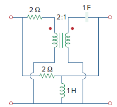
Figure 19.116
Find the admittance parameters for the given two-port network in Figure 19.116 in the textbook.
Answer to Problem 69P
The admittance parameters for the given two-port network are
Explanation of Solution
Given Data:
Refer to Figure 19.116 in the textbook for the given two-port network.
Formula used:
Write the expressions for admittance parameters of a two-port network as follows:
Calculation:
Note that the dimensions are neglected for simple calculations.
Consider upper network as network
As the interconnection network is a parallel combination of two networks, it is easier to obtain the required objective in terms of admittance parameters. Find the admittance parameters for upper and lower network and add them to obtain the overall admittance parameters.
The admittance parameters
Redraw the upper network by short circuiting the port-2 as shown in Figure 1.
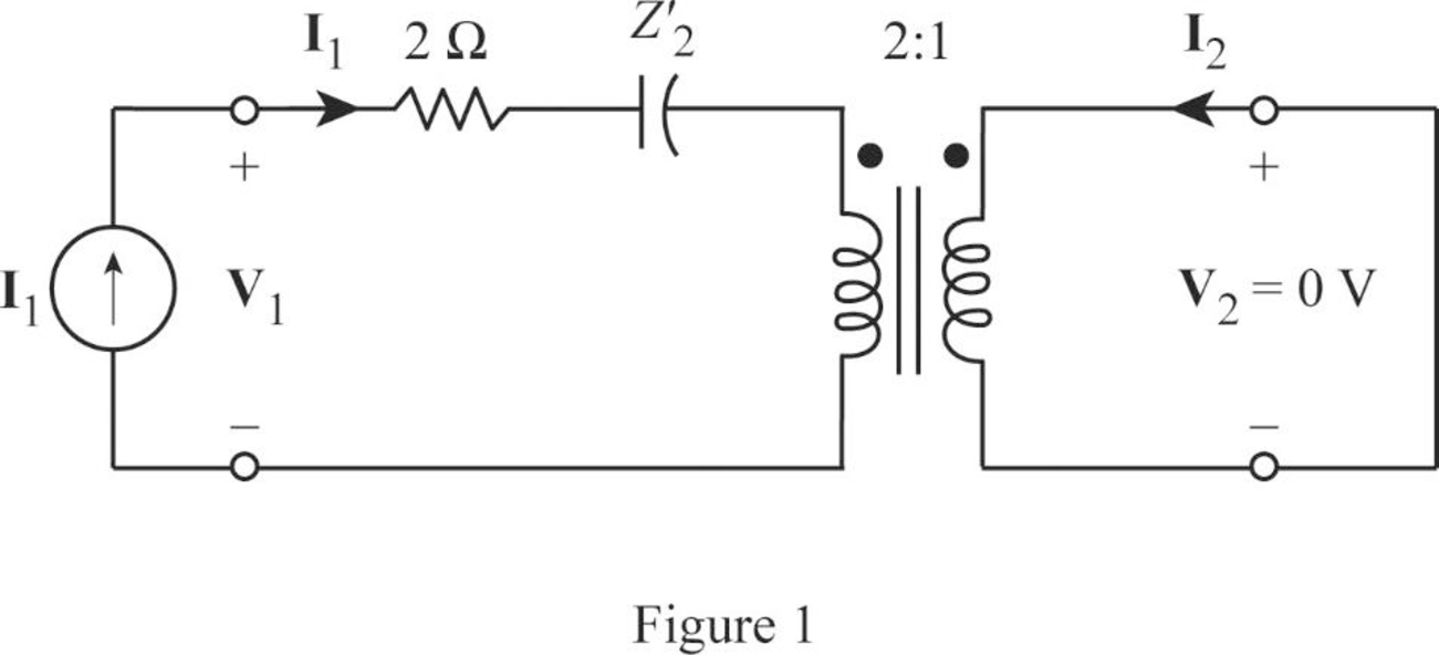
Write the expression for equivalent impedance of secondary winding capacitance when the transformer is referred to the primary winding as follows:
Here,
Substitute
From Figure 1, write the expression for
Substitute
Rearrange the expression as follows:
Substitute
From Figure 1, write the expression for
From Equation (6), substitute
Rearrange the expression as follows:
Substitute
The admittance parameters
Redraw the given two-port network by short circuiting the port-1 as shown in Figure 2.
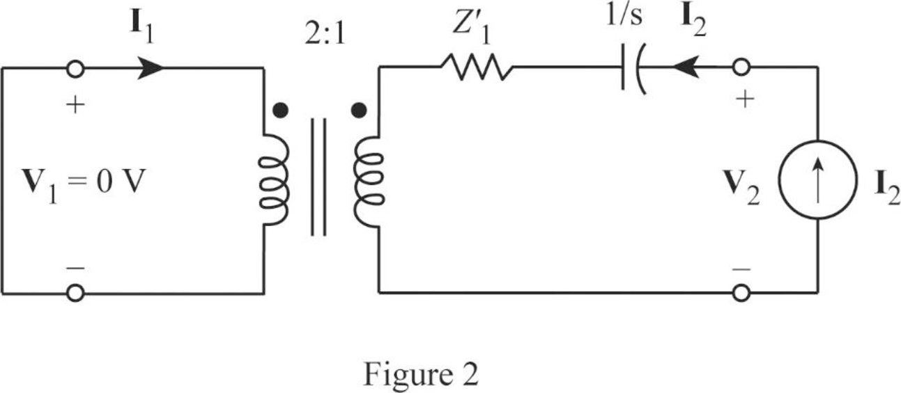
Write the expression for equivalent impedance of primary winding resistance when the transformer is referred to the secondary winding as follows:
Here,
Substitute
From Figure2, write the expression for
Substitute 0.5 for
Rearrange the expression as follows:
Substitute
From Figure 1, write the expression for
From Equation (10), substitute
Rearrange the expression as follows:
Substitute
From the calculations, write the y-parameters for upper network as follows:
Redraw the lower network by short circuiting the port-2 as shown in Figure 3.
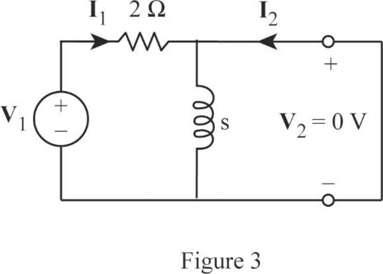
As the current bypasses through the short circuit path, redraw the circuit in Figure 3 as shown in Figure 4.
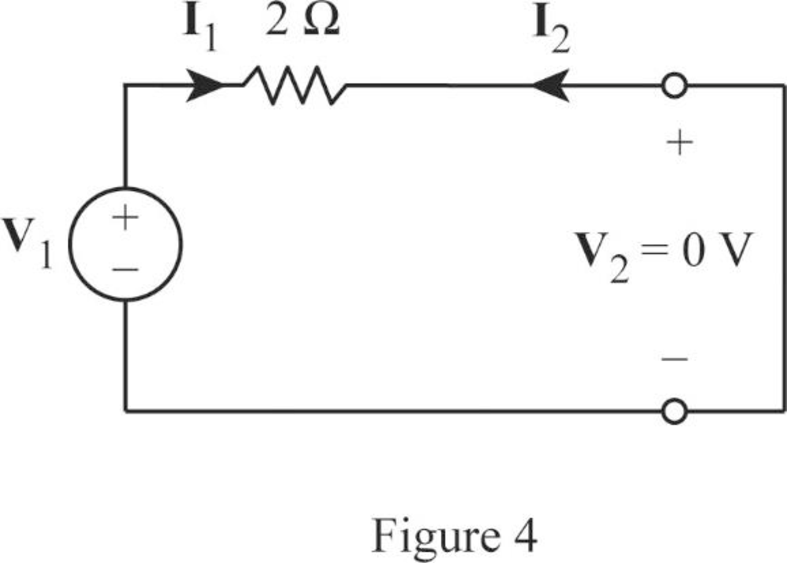
From Figure 4, write the expression for
Rearrange the expression as follows:
Substitute 0.5 for
From Figure 1, the expression for current
From Equation (11), substitute
Rearrange the expression as follows:
Substitute
Redraw the lower network by short circuiting the port-1 as shown in Figure 5.
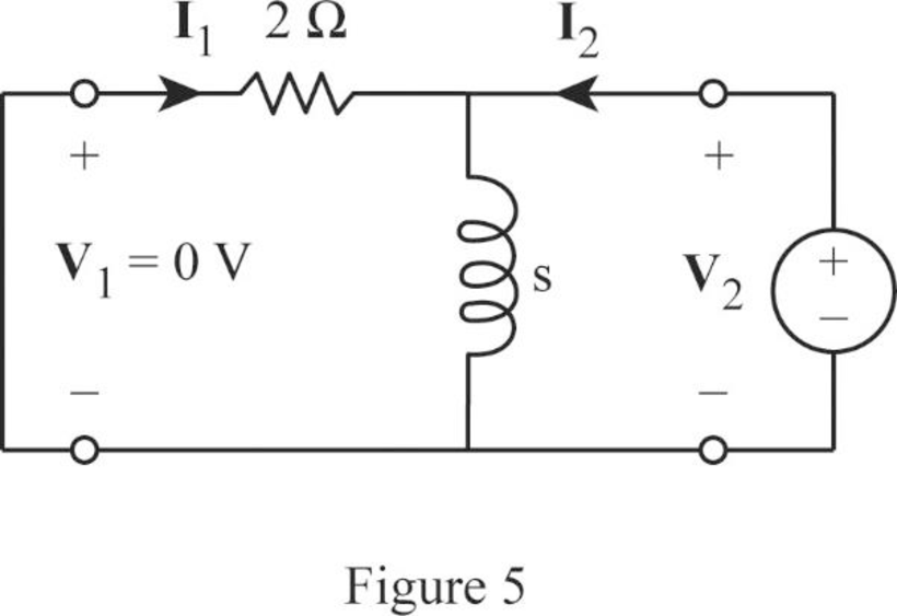
From Figure 5, write the expression for
Rearrange the expression as follows:
Substitute
From Figure 5, obtain the current
From Equation (12), substitute
Rearrange the expression as follows:
Substitute
From the calculations, write the y-parameters for lower network as follows:
As the upper and lower networks are connected in parallel, write the expression for overall admittance parameters as follows:
Substitute
Simplify the expression as follows:
Conclusion:
Thus, the admittance parameters for the given two-port network are
Want to see more full solutions like this?
Chapter 19 Solutions
EBK FUNDAMENTALS OF ELECTRIC CIRCUITS


- An AM modulation waveform signal:- p(t)=(8+4 cos 1000πt + 4 cos 2000πt) cos 10000nt (a) Sketch the amplitude spectrum of p(t). (b) Find total power, sideband power and power efficiency. (c) Find the average power containing of each sideband.arrow_forwardCan you rewrite the solution because it is unclear? AM (+) = 8(1+ 0.5 cos 1000kt +0.5 ros 2000ks) = cos 10000 πt. 8 cos wat + 4 cos wit + 4 cos Wat coswet. -Jet jooort J11000 t = 4 e jqooort jgoort +4e + e +e j 12000rt. 12000 kt + e +e jooxt igoo t te (w) = 8ES(W- 100007) + 8IS (W-10000) USBarrow_forwardCan you rewrite the solution because it is unclear? AM (+) = 8(1+0.5 cos 1000kt +0.5 ros 2000 thts) = cos 10000 πt. 8 cos wat + 4 cos wit + 4 cos Wat coswet. J4000 t j11000rt $14+) = 45 jqooort +4e + e + e j 12000rt. 12000 kt + e +e +e Le jsoort -; goon t te +e Dcw> = 885(W- 100007) + 8 IS (W-10000) - USBarrow_forward
- Can you rewrite the solution because it is unclear? Q2 AM ①(+) = 8 (1+0.5 cos 1000πt +0.5 ros 2000kt) $4+) = 45 = *cos 10000 πt. 8 cos wat + 4 cosat + 4 cos Wat coswet. j1000016 +4e -j10000πt j11000Rt j gooort -j 9000 πt + e +e j sooort te +e J11000 t + e te j 12000rt. -J12000 kt + с = 8th S(W- 100007) + 8 IS (W-10000) <&(w) = USB -5-5 -4-5-4 b) Pc 2² = 64 PSB = 42 + 4 2 Pt Pc+ PSB = y = Pe c) Puss = PLSB = = 32 4² = 8 w 32+ 8 = × 100% = 140 (1)³×2×2 31 = 20% x 2 = 3w 302 USB 4.5 5 5.6 6 ms Ac = 4 mi = 0.5 mz Ac = 4 ५ M2 = =0.5arrow_forwardA. Draw the waveform for the following binary sequence using Bipolar RZ, Bipolar NRZ, and Manchester code. Data sequence= (00110100) B. In a binary PCM system, the output signal-to-quantization ratio is to be hold to a minimum of 50 dB. If the message is a single tone with fm-5 kHz. Determine: 1) The number of required levels, and the corresponding output signal-to-quantizing noise ratio. 2) Minimum required system bandwidth.arrow_forwardFind Io using Mesh analysisarrow_forward
- FM station of 100 MHz carrier frequency modulated by a 20 kHz sinusoid with an amplitude of 10 volt, so that the peak frequency deviation is 25 kHz determine: 1) The BW of the FM signal. 2) The approximated BW if the modulating signal amplitude is increased to 50 volt. 3) The approximated BW if the modulating signal frequency is increased by 70%. 4) The amplitude of the modulating signal if the BW is 65 kHz.arrow_forwardAn FDM is used to multiplex two groups of signals using AM-SSB, the first group contains 25 speech signals, each has maximum frequency of 4 kHz, the second group contains 15 music signals, each has maximum frequency of 10 kHz. A guard bandwidth of 500 Hz is used bety each two signals and before the first one. 1. Find the BWmultiplexing 2. Find the BWtransmission if the multiplexing signal is modulated using AM-DSB-LC.arrow_forwardAn FM signal with 75 kHz deviation, has an input signal-to-noise ratio of 18 dB, with a modulating frequency of 15 kHz. 1) Find SNRO at demodulator o/p. 2) Find SNRO at demodulator o/p if AM is used with m=0.3. 3) Compare the performance in case 1) and 2).. Hint: for single tone AM-DSB-LC, SNR₁ = (2m²) (4)arrow_forward
 Introductory Circuit Analysis (13th Edition)Electrical EngineeringISBN:9780133923605Author:Robert L. BoylestadPublisher:PEARSON
 Delmar's Standard Textbook Of ElectricityElectrical EngineeringISBN:9781337900348Author:Stephen L. HermanPublisher:Cengage Learning
 Programmable Logic ControllersElectrical EngineeringISBN:9780073373843Author:Frank D. PetruzellaPublisher:McGraw-Hill Education
 Fundamentals of Electric CircuitsElectrical EngineeringISBN:9780078028229Author:Charles K Alexander, Matthew SadikuPublisher:McGraw-Hill Education
 Electric Circuits. (11th Edition)Electrical EngineeringISBN:9780134746968Author:James W. Nilsson, Susan RiedelPublisher:PEARSON
 Engineering ElectromagneticsElectrical EngineeringISBN:9780078028151Author:Hayt, William H. (william Hart), Jr, BUCK, John A.Publisher:Mcgraw-hill Education,