
EBK FUNDAMENTALS OF ELECTRIC CIRCUITS
6th Edition
ISBN: 8220102801448
Author: Alexander
Publisher: YUZU
expand_more
expand_more
format_list_bulleted
Videos
Textbook Question
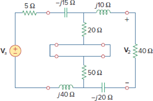
Chapter 19.7, Problem 12PP
Find V2/Vs in the circuit in Fig. 19.43.
Figure 19.43
Expert Solution & Answer
Want to see the full answer?
Check out a sample textbook solution
Students have asked these similar questions
I need help with this problem and an step by step explanation of the solution from the image described below. (Introduction to Signals and Systems)
I need help with this problem and an step by step explanation of the solution from the image described below. (Introduction to Signals and Systems)
I need help with this problem and an step by step explanation of the solution from the image described below. (Introduction to Signals and Systems)
Chapter 19 Solutions
EBK FUNDAMENTALS OF ELECTRIC CIRCUITS
Ch. 19.2 - Find the z parameters of the two-port network in...Ch. 19.2 - Calculate I1 and I2 in the two-port of Fig. 19.11....Ch. 19.3 - Obtain the y parameters for the T network shown in...Ch. 19.3 - Obtain the y parameters for the circuit in Fig....Ch. 19.4 - Determine the h parameters for the circuit in Fig....Ch. 19.4 - Find the impedance at the input port of the...Ch. 19.4 - For the ladder network in Fig. 19.30, determine...Ch. 19.5 - Find the transmission parameters for the circuit...Ch. 19.5 - Prob. 9PPCh. 19.6 - Determine [y] and [T] of a two-port network whose...
Ch. 19.6 - Find the z parameters of the op amp circuit in...Ch. 19.7 - Find V2/Vs in the circuit in Fig. 19.43. Figure...Ch. 19.7 - Obtain the y parameters for the network in Fig....Ch. 19.7 - Obtain the ABCD parameter representation of the...Ch. 19.8 - Obtain the h parameters for the network in Fig....Ch. 19.8 - Obtain the z parameters of the circuit in Fig....Ch. 19.9 - For the transistor amplifier of Fig. 19.60, find...Ch. 19.9 - Prob. 18PPCh. 19 - For the single-element two-port network in Fig....Ch. 19 - For the single-element two-port network in Fig....Ch. 19 - For the single-element two-port network in Fig....Ch. 19 - For the single-element two-port network in Fig....Ch. 19 - For the single-element two-port network in Fig....Ch. 19 - For the single-element two-port network in Fig....Ch. 19 - When port 1 of a two-port circuit is...Ch. 19 - A two-port is described by the following...Ch. 19 - If a two-port is reciprocal, which of the...Ch. 19 - Prob. 10RQCh. 19 - Obtain the z parameters for the network in Fig....Ch. 19 - Find the impedance parameter equivalent of the...Ch. 19 - Find the z parameters of the circuit in Fig....Ch. 19 - Using Fig. 19.68, design a problem to help other...Ch. 19 - Obtain the z parameters for the network in Fig....Ch. 19 - Compute the z parameters of the circuit in Fig....Ch. 19 - Calculate the z parameters of the circuit in Fig....Ch. 19 - Find the z parameters of the two-port in Fig....Ch. 19 - The y parameters of a network are:...Ch. 19 - Construct a two-port that realizes each of the...Ch. 19 - Determine a two-port network that is represeted by...Ch. 19 - For the circuit shown in Fig. 19.73, let z=106412...Ch. 19 - Determine the average power delivered to ZL = 5 +...Ch. 19 - For the two-port network shown in Fig. 19.75, show...Ch. 19 - For the two-port circuit in Fig. 19.76,...Ch. 19 - For the circuit in Fig. 19.77, at = 2 rad/s, z11...Ch. 19 - Prob. 17PCh. 19 - Calculate the y parameters for the two-port in...Ch. 19 - Using Fig. 19.80, design a problem to help other...Ch. 19 - Find the y parameters for the circuit in Fig....Ch. 19 - Obtain the admittance parameter equivalent circuit...Ch. 19 - Obtain the y parameters of the two-port network in...Ch. 19 - (a) Find the y parameters of the two-port in Fig....Ch. 19 - Find the resistive circuit that represents these y...Ch. 19 - Prob. 25PCh. 19 - Calculate [y] for tle two-port in Fig. 19.85.Ch. 19 - Find the y parameters for the Circuit in Fig....Ch. 19 - In the circuit of Fig. 19.65, the input port is...Ch. 19 - In the bridge circuit of Fig. 19.87, I1 = 20 A and...Ch. 19 - Find the h parameters for the networks in Fig....Ch. 19 - Determine the hybrid parameters for the network in...Ch. 19 - Using Fig. 19.90, design a problem to help other...Ch. 19 - Obtain the h parameters for the two-port of Fig....Ch. 19 - Obtain the h and g parameters of the two-port in...Ch. 19 - Determine the h parameters for the network in Fig....Ch. 19 - For the two-port in Fig. 19.94. h=16320.01S Find:...Ch. 19 - The input port of the circuit in Fig. 19.79 is...Ch. 19 - The h parameters of the two-port of Fig. 19.95...Ch. 19 - Obtain the g parameters for the wye circuit of...Ch. 19 - Using Fig. 19.97, design a problem to help other...Ch. 19 - For the two-port in Fig. 19.75, show that...Ch. 19 - The h parameters of a two-port device are given by...Ch. 19 - Find the transmission parameters for the...Ch. 19 - Using Fig. 19.99, design a problem to help other...Ch. 19 - Find the ABCD parameters for the circuit in Fig....Ch. 19 - Find the transmission parameters for the circuit...Ch. 19 - Obtain the ABCD parameters for the network in Fig....Ch. 19 - For a two-port, let A = 4, B = 30 , C = 0.1 S, and...Ch. 19 - Using impedances in the s-domain, obtain the...Ch. 19 - Derive the s-domain expression for the t...Ch. 19 - Obtain the t parameters for the network in Fig....Ch. 19 - (a) For the T network in Fig. 19.106, show that...Ch. 19 - Prob. 53PCh. 19 - Show that the transmission parameters of a...Ch. 19 - Prove that the g parameters can be obtained from z...Ch. 19 - For the network of Fig. 19.107, obtain VoVs....Ch. 19 - Given the transmission parameters T=32017 obtain...Ch. 19 - Design a problem to help other students better...Ch. 19 - Given that g=0.06S0.40.22 determine: (a) [z] (b)...Ch. 19 - Design a T network necessary to realize the...Ch. 19 - For the bridge circuit in Fig. 19.108, obtain: (a)...Ch. 19 - Find the z parameters of the op amp circuit in...Ch. 19 - Determine the z parameters of the two-port in Fig....Ch. 19 - Determine the y parameters at = 1,000 rad/s for...Ch. 19 - What is the y parameter presentation of the...Ch. 19 - In the two-port of Fig. 19.113, let y12 = y21 = 0,...Ch. 19 - If three copies of the circuit in Fig. 19.114 are...Ch. 19 - Obtain the h parameters for the network in Fig....Ch. 19 - The circuit in Fig. 19.116 may be regarded as two...Ch. 19 - For the parallel-series connection of the two...Ch. 19 - Determine the z parameters for the network in Fig....Ch. 19 - A series-parallel connection of two two-ports is...Ch. 19 - Three copies of the circuit shown in Fig. 19.70...Ch. 19 - Determine the ABCD parameters of the circuit in...Ch. 19 - For the individual two-ports shown in Fig. 19.121...Ch. 19 - Use PSpice or MultiSim to obtain the z parameters...Ch. 19 - Using PSpice or MultiSim, find the h parameters of...Ch. 19 - Obtain the h parameters at = 4 rad/s for the...Ch. 19 - Use PSpice or MultiSim to determine the z...Ch. 19 - Use PSpice or MultiSim to find the z parameters of...Ch. 19 - Repeat Prob. 19.26 using PSpice or MultiSim....Ch. 19 - Use PSpice or MultiSim to rework Prob. 19.31....Ch. 19 - Rework Prob. 19.47 using PSpice or MultiSim....Ch. 19 - Using PSpice or MultiSim, find the transmission...Ch. 19 - At =1rad/s, find the transmission parameters of...Ch. 19 - Obtain the g parameters for the network in Fig....Ch. 19 - For the circuit shown in Fig. 19.129, use PSpice...Ch. 19 - Using the y parameters, derive formulas for Zin,...Ch. 19 - A transistor has the following parameters in a...Ch. 19 - A transistor with hfe=120,hie=2khre=104,hoe=20S is...Ch. 19 - For the transistor network of Fig. 19.130,...Ch. 19 - Prob. 92PCh. 19 - Prob. 93PCh. 19 - A transistor in its common-emitter mode is...Ch. 19 - Prob. 95PCh. 19 - Prob. 96PCh. 19 - Synthesize the transfer function...Ch. 19 - A two-stage amplifier in Fig. 19.134 contains two...Ch. 19 - Assume that the two circuits in Fig. 19.135 are...
Additional Engineering Textbook Solutions
Find more solutions based on key concepts
How are relationships between tables expressed in a relational database?
Modern Database Management
Consider the adage Never ask a question for which you do not want the answer. a. Is following that adage ethica...
Experiencing MIS
1.2 Explain the difference between geodetic and plane
surveys,
Elementary Surveying: An Introduction To Geomatics (15th Edition)
What is an uninitialized variable?
Starting Out with Programming Logic and Design (5th Edition) (What's New in Computer Science)
This optional Google account security feature sends you a message with a code that you must enter, in addition ...
SURVEY OF OPERATING SYSTEMS
How does a computers main memory differ from its auxiliary memory?
Java: An Introduction to Problem Solving and Programming (8th Edition)
Knowledge Booster


Learn more about
Need a deep-dive on the concept behind this application? Look no further. Learn more about this topic, electrical-engineering and related others by exploring similar questions and additional content below.Similar questions
- I need help with this problem and an step by step explanation of the solution from the image described below. (Introduction to Signals and Systems)arrow_forwardI need help with this problem and an step by step explanation of the solution from the image described below. (Introduction to Signals and Systems)arrow_forward2) Design the circuit shown in Figure 2 to provide bias current of IQ2= 150 uA. Assume circuit parameters of IREF2 = 250 UA, V+ = 3 V, and V = -3 V. The transistor parameters are VTP = -0.6 V, λ = 0, K'p= 40 uA/V², W/Lc = 15 and W/LA = 25. V+ Mc + VSGC VSGB + MB VSGA + + MA VSDA IREF2 V- Figure 2 ww RD=8kQarrow_forward
- ٣/١ a い يكا +91- PU + 96852 A. For the RL-circuit with i(0)=0, Find the current i(t) using LT R=2 V(t)=sin3t L=1H B. Find Invers Laplace Transform for Z(s) = = 220125 750 x2.01 4s2 +2s+3 s2-3s+2arrow_forward1) Taking base current into account, determine the value of I copy in each circuit depicted in Fig 1. Normalize the error to nominal value of Icopy. REF Vcc AE Vcc QREF Figure 1- a I copy 5AE REF 12 Q₁ copy Q2 5AE 2AE ЗАЕ QREF Figure 1-barrow_forward12.2 Evaluate each of the following integrals. (a) G₁: = = √ (31³ +21² + 1) [8(t) +48 (t − 2)] dt -21 (b) G₂ = G2 = 4(e¯2ª +1)[☎(t) −28(t − 2)] dt -2 -20 (c) G3 = 0 3( cos 2π- 1) [8(t) +☎(t − 10)] dt -20arrow_forward
- 3) The differential amplifier in Figure 3 is biased with a three-transistor current source. The transistor parameters are ẞ= 100, VBE (on) = 0.7 V, and VA = ∞. a) Determine I1. Ic2, IC4, VCE2, and VCE4. b) Determine a new value of R1 such that VCE4 = 2.5V. what are the values of Ic4, Ic2, I1, and R₁? +5 V Q1 R₁ = 8.5 ΚΩ IC4 23 RC= • 2 ΚΩ + 24 VCE4 RC= 2 ΚΩ est Ic2 + Q2 VCE2 -5 V Figure 3arrow_forward12.1 Evaluate each of the following integrals: (a) G₁ = √(33-4t²+3)[8(t) +28(t − 2)] dt. (b) G₂ = √442(e³ +1)[8(t) − 28(t − 2)] dt. .16 -31 (c) G3=124t sin(2лt) − 1][§(t − 1) +☎(t − 6)] dt.arrow_forwardWhy is the voltage drop of a self-excited generator greater than the voltagedrop of a separately excited generator?arrow_forward
- When driving a DC shunt generator with a synchronous prime mover motor, why does the AC amperage to the synchronous motor machine increase as load is added to the generator?arrow_forward100 What is the phase and gain margins of the following system, is it stable or not. Design a PI controller for the following unstable process if any. 50 -120 -130 0 -140 -50 -150 -100 -160 <<-150 -170 -200 -180 10-1 10° 10¹ 102 103 104 105 1071 10° 10¹ 102 103 101 105 Frequency (rad/s) Frequency (rad/s)arrow_forwardPlease assist in the below questionarrow_forward
arrow_back_ios
SEE MORE QUESTIONS
arrow_forward_ios
Recommended textbooks for you
 Introductory Circuit Analysis (13th Edition)Electrical EngineeringISBN:9780133923605Author:Robert L. BoylestadPublisher:PEARSON
 Delmar's Standard Textbook Of ElectricityElectrical EngineeringISBN:9781337900348Author:Stephen L. HermanPublisher:Cengage Learning
 Programmable Logic ControllersElectrical EngineeringISBN:9780073373843Author:Frank D. PetruzellaPublisher:McGraw-Hill Education
 Fundamentals of Electric CircuitsElectrical EngineeringISBN:9780078028229Author:Charles K Alexander, Matthew SadikuPublisher:McGraw-Hill Education
 Electric Circuits. (11th Edition)Electrical EngineeringISBN:9780134746968Author:James W. Nilsson, Susan RiedelPublisher:PEARSON
 Engineering ElectromagneticsElectrical EngineeringISBN:9780078028151Author:Hayt, William H. (william Hart), Jr, BUCK, John A.Publisher:Mcgraw-hill Education,
Introductory Circuit Analysis (13th Edition)
Electrical Engineering
ISBN:9780133923605
Author:Robert L. Boylestad
Publisher:PEARSON
Delmar's Standard Textbook Of Electricity
Electrical Engineering
ISBN:9781337900348
Author:Stephen L. Herman
Publisher:Cengage Learning
Programmable Logic Controllers
Electrical Engineering
ISBN:9780073373843
Author:Frank D. Petruzella
Publisher:McGraw-Hill Education
Fundamentals of Electric Circuits
Electrical Engineering
ISBN:9780078028229
Author:Charles K Alexander, Matthew Sadiku
Publisher:McGraw-Hill Education
Electric Circuits. (11th Edition)
Electrical Engineering
ISBN:9780134746968
Author:James W. Nilsson, Susan Riedel
Publisher:PEARSON
Engineering Electromagnetics
Electrical Engineering
ISBN:9780078028151
Author:Hayt, William H. (william Hart), Jr, BUCK, John A.
Publisher:Mcgraw-hill Education,
Introduction to Two-Port Networks; Author: ALL ABOUT ELECTRONICS;https://www.youtube.com/watch?v=ru2ItcD6unI;License: Standard Youtube License