
Concept explainers
Videos
A two-stage amplifier in Fig. 19.134 contains two identical stages with
If ZL = 20 kΩ, find the required value of Vs to produce Vo = 16 V.
![Chapter 19, Problem 98P, A two-stage amplifier in Fig. 19.134 contains two identical stages with [h]=2k0.004200500S If ZL =](http://dev-ingestion-image-output.s3-website-us-east-1.amazonaws.com/9780078028229/Chapter-19/images/28229-19-98p-question-digital_image_001.png)
Figure 19.134
Calculate the required source voltage for the given two-stage amplifier.
Answer to Problem 98P
The required source voltage for the given two-stage amplifier is
Explanation of Solution
Given Data:
The h parameters of each stage of the amplifier are given as follows:
The load impedance and output voltage of the given two-stage amplifier are given as follows:
Refer to Figure 19.134 in the textbook for the given two-stage amplifier circuit.
Formula used:
Refer to TABLE 19.1 in the textbook, write the expression for transmission parameters in terms of h parameters as follows:
Write the expression for
Write the expression for
From TABLE 19.1 in the textbook, write the expression for impedance parameters in terms of transmission parameters as follows:
Calculation:
From the given circuit, the two-stage amplifier is the cascade connection of two identical transistors. Obtain the transmission parameters for two-stage amplifier and then convert into impedance parameters for simple analysis.
Find the transmission parameters for one stage of the two-stage amplifier as follows:
Substitute
Substitute
As both the stages are identical, the transmission parameters of second stage of the amplifier are equal to the first stage.
As the two identical stages are connected in cascade to form a two-stage amplifier, write the expression for overall transmission parameters for the amplifier as follows:
Substitute
From the obtained transmission parameters of the two-stage amplifier, write the transmission parameters as follows:
Convert the obtained transmission parameters into impedance parameters as follows:
Substitute
Substitute
Refer to Figure 19.5 (b) in the textbook for general equivalent circuit of impedance parameters and draw the circuit for given amplifier as shown in Figure 1.
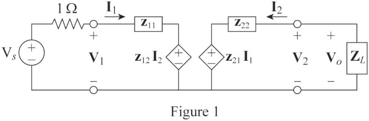
From the circuit in Figure 1, apply KVL to the input loop as follows:
Simplify the expression as follows:
From the circuit in Figure 1, apply KVL to the output loop as follows:
Simplify the expression as follows:
From Figure 1, write the expression for
Rearrange the expression as follows:
Substitute
From Equations (7) and (8), substitute
Substitute
Simplify the expression as follows:
Conclusion:
Thus, the required source voltage for the given two-stage amplifier is
Want to see more full solutions like this?
Chapter 19 Solutions
EBK FUNDAMENTALS OF ELECTRIC CIRCUITS


- + V 6.2 A 1.2 A S R 4 Ω Find the source voltage Vs 0.8 Aarrow_forwardDetermine i(t) for t≥ 0 given that the circuit below had been in steady state for a long time prior to t = 0. Also, I₁ = 1 5 A, R₁ =22, R2 =10 Q2, R3 = 32, R4 =7 2, and L=0.15 H. Also fill the table. m L ww R2 t = 0 R₁ 29 R3 R4 Time 0 iL(t) 0 8arrow_forwardPlease help explain this problemarrow_forward
- + P = 16 W w w P = 8 W I R₁ R2 E = RT=322 1- Determine R1, R2, E ΙΩarrow_forward+ 30 V = - 20 V + R 2- Use KVL to find the voltage V - V + + 8 Varrow_forwardFind the Thévenin equivalent circuit for the portions of the networks in Figure external to the elements between points a and b. a R₁ 2002 I = 0.1 A 0° Xc : 32 Ω R2 = 6802 20 Ω фъarrow_forward
- Find the Norton equivalent circuit for the network external to the elements between a and b for the networks in Figure. E1 = 120 V Z 0° R ww 10 Ω Xc XL · 000 802 802 ① I = 0.5 AZ 60° ZL barrow_forwardUsing superposition, determine the current through inductance XL for each network in Figure I = 0.3 A 60° XL 000 802 XC 502 Ω E 10 V0° =arrow_forwardFind the Thévenin equivalent circuit for the portions of the networks in Figure external to the elements between points a and b. E = 20 VZ0° + R ww 2 ΚΩ Хо XL 000 6ΚΩ 3 ΚΩ b RLarrow_forward
- What percentage of the full-load current of a thermally protected continuous-duty motor of more than one Hp can the trip current be, if the full-load current is 15 amperes? Ο 122 Ο 140 156 O 170arrow_forwardQ3arrow_forwardIn thinkercad can you make a parallel series circuit with a resistors and a voltage source explain how the voltage and current moves through the circuit, and explaining all the components, and if you were to break the circuit to find the current how would you do that? Please show visuals if possible.arrow_forward
 Introductory Circuit Analysis (13th Edition)Electrical EngineeringISBN:9780133923605Author:Robert L. BoylestadPublisher:PEARSON
 Delmar's Standard Textbook Of ElectricityElectrical EngineeringISBN:9781337900348Author:Stephen L. HermanPublisher:Cengage Learning
 Programmable Logic ControllersElectrical EngineeringISBN:9780073373843Author:Frank D. PetruzellaPublisher:McGraw-Hill Education
 Fundamentals of Electric CircuitsElectrical EngineeringISBN:9780078028229Author:Charles K Alexander, Matthew SadikuPublisher:McGraw-Hill Education
 Electric Circuits. (11th Edition)Electrical EngineeringISBN:9780134746968Author:James W. Nilsson, Susan RiedelPublisher:PEARSON
 Engineering ElectromagneticsElectrical EngineeringISBN:9780078028151Author:Hayt, William H. (william Hart), Jr, BUCK, John A.Publisher:Mcgraw-hill Education,