GO Figure 18-46 shows the cross section of a wall made of three layers. The layer thicknesses are L 1 , L 2 = 0.700 L 1 , and L 3 = 0.350 L 1 . The thermal conductivities are k 1 , k 2 = 0.900 k 1 , and k 3 = 0.800 k 1 . The temperatures at the left side and right side of the wall are T H = 30.0°C and T C = −15.0°C, respectively. Thermal conduction is steady. (a) What is the temperature difference Δ T 2 across layer 2 (between the left and right sides of the layer)? If k 2 were, instead, equal to 1.1 k 1 , (b) would the rate at which energy is conducted through the wall be greater than, less than, or the same as previously, and (c) what would be the value of Δ T 2 ? Figure 18-56 Problem 60.
GO Figure 18-46 shows the cross section of a wall made of three layers. The layer thicknesses are L 1 , L 2 = 0.700 L 1 , and L 3 = 0.350 L 1 . The thermal conductivities are k 1 , k 2 = 0.900 k 1 , and k 3 = 0.800 k 1 . The temperatures at the left side and right side of the wall are T H = 30.0°C and T C = −15.0°C, respectively. Thermal conduction is steady. (a) What is the temperature difference Δ T 2 across layer 2 (between the left and right sides of the layer)? If k 2 were, instead, equal to 1.1 k 1 , (b) would the rate at which energy is conducted through the wall be greater than, less than, or the same as previously, and (c) what would be the value of Δ T 2 ? Figure 18-56 Problem 60.
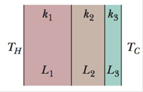
GO Figure 18-46 shows the cross section of a wall made of three layers. The layer thicknesses are L1, L2 = 0.700L1, and L3 = 0.350L1. The thermal conductivities are k1, k2 = 0.900 k1, and k3 = 0.800 k1. The temperatures at the left side and right side of the wall are TH = 30.0°C and TC = −15.0°C, respectively. Thermal conduction is steady. (a) What is the temperature difference ΔT2 across layer 2 (between the left and right sides of the layer)? If k2 were, instead, equal to 1.1k1, (b) would the rate at which energy is conducted through the wall be greater than, less than, or the same as previously, and (c) what would be the value of ΔT2?
For each of the actions depicted below, a magnet and/or metal loop moves with velocity v→ (v→ is constant and has the same magnitude in all parts). Determine whether a current is induced in the metal loop. If so, indicate the direction of the current in the loop, either clockwise or counterclockwise when seen from the right of the loop. The axis of the magnet is lined up with the center of the loop. For the action depicted in (Figure 5), indicate the direction of the induced current in the loop (clockwise, counterclockwise or zero, when seen from the right of the loop). I know that the current is clockwise, I just dont understand why. Please fully explain why it's clockwise, Thank you
A planar double pendulum consists of two point masses \[m_1 = 1.00~\mathrm{kg}, \qquad m_2 = 1.00~\mathrm{kg}\]connected by massless, rigid rods of lengths \[L_1 = 1.00~\mathrm{m}, \qquad L_2 = 1.20~\mathrm{m}.\]The upper rod is hinged to a fixed pivot; gravity acts vertically downward with\[g = 9.81~\mathrm{m\,s^{-2}}.\]Define the generalized coordinates \(\theta_1,\theta_2\) as the angles each rod makes with thedownward vertical (positive anticlockwise, measured in radians unless stated otherwise).At \(t=0\) the system is released from rest with \[\theta_1(0)=120^{\circ}, \qquad\theta_2(0)=-10^{\circ}, \qquad\dot{\theta}_1(0)=\dot{\theta}_2(0)=0 .\]Using the exact nonlinear equations of motion (no small-angle or planar-pendulumapproximations) and assuming the rods never stretch or slip, determine the angle\(\theta_2\) at the instant\[t = 10.0~\mathrm{s}.\]Give the result in degrees, in the interval \((-180^{\circ},180^{\circ}]\).
What are the expected readings of the ammeter and voltmeter for the circuit in the figure below? (R = 5.60 Ω, ΔV = 6.30 V)
ammeter
I =
Need a deep-dive on the concept behind this application? Look no further. Learn more about this topic, physics and related others by exploring similar questions and additional content below.


 Principles of Physics: A Calculus-Based TextPhysicsISBN:9781133104261Author:Raymond A. Serway, John W. JewettPublisher:Cengage Learning
 Physics for Scientists and Engineers: Foundations...PhysicsISBN:9781133939146Author:Katz, Debora M.Publisher:Cengage Learning
 College PhysicsPhysicsISBN:9781285737027Author:Raymond A. Serway, Chris VuillePublisher:Cengage Learning
 Physics for Scientists and Engineers with Modern ...PhysicsISBN:9781337553292Author:Raymond A. Serway, John W. JewettPublisher:Cengage Learning
 Physics for Scientists and Engineers, Technology ...PhysicsISBN:9781305116399Author:Raymond A. Serway, John W. JewettPublisher:Cengage Learning