
Laboratory Manual for Introductory Circuit Analysis
13th Edition
ISBN: 9780133923780
Author: Robert L. Boylestad, Gabriel Kousourou
Publisher: PEARSON
expand_more
expand_more
format_list_bulleted
Videos
Textbook Question
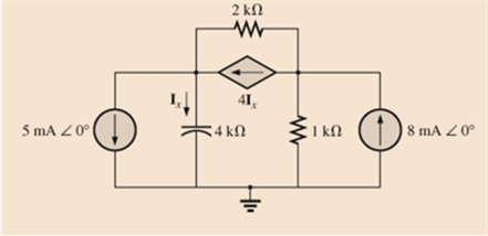
Chapter 18, Problem 25P
Write the nodal equations for the network in Fig. 18.83, and find the voltage across the 1 k
Expert Solution & Answer
Want to see the full answer?
Check out a sample textbook solution
Students have asked these similar questions
type (o)
bT
S+αT
Profational controller
a = b = 5, T-La
|kp|
50
5+50
kp=20,50,70
② type (1)
bT
5(stat)
a=b=5,T= 1
✓ KT
5
SC5+5
kp=20, 50, 70
(Find Wny, ess for type (a) and (1))
2.
Write an expression of the two sinusoidal voltage waveforms whose effective value
is 7.071 V and whose phase difference is 90 degrees. Draw the phasor of those two sinusoidal
waveforms in the complex plane.
2. Determine developed torque and shaft torque of 220-V, 4-pole series motor with 800 conductors
wave-connected supplying a load of 8.2kW by taking 45A from the mains. The flux per pole is 25 mWb
and its armature circuit resistance is 0.60.
Ans.[143.25 Nm, 135.25 Nm]
Chapter 18 Solutions
Laboratory Manual for Introductory Circuit Analysis
Ch. 18 - Discuss, in your own words, the difference between...Ch. 18 - Convert the voltage source in Fig. 18.62 to a...Ch. 18 - Convert the current source in Fig. 18.63 to a...Ch. 18 - Convert the votage source in Fig. 18.64(a) to a...Ch. 18 - Write the mesh equations for the network of Fig....Ch. 18 - Write the mesh equations for the network of Fig....Ch. 18 - Write the mesh equations for the network of Fig....Ch. 18 - Write the mesh equations for the network of Fig....Ch. 18 - Write the mesh equations for the network of Fig....Ch. 18 - Write the mesh equtions for the network of Fig....
Ch. 18 - Write the mesh equations for the network of Fig....Ch. 18 - Using mesh analysis, determine the current IL (in...Ch. 18 - Using mesh analysis, determine the current IL (in...Ch. 18 - Write the mesh equations for the network of Fig....Ch. 18 - Write the mesh equations for the network of...Ch. 18 - Write the mesh equations for the network of Fig....Ch. 18 - Determine the nodal voltages for the network of...Ch. 18 - Determine the nodal voltages for the network of...Ch. 18 - Determine the nodal voltages for the network of...Ch. 18 - Determine the nodal voltages for the network of...Ch. 18 - Determine the nodal voltages for the network of...Ch. 18 - Determine the nodal voltages for the network of...Ch. 18 - Determine the nodal votas for the network of Fig....Ch. 18 - Determine the nodal voltages for the network of...Ch. 18 - Write the nodal equations for the network in Fig....Ch. 18 - Write the nodal equations for the network of Fig....Ch. 18 - Write the nodal equations for the network of Fig....Ch. 18 - Write the nodal equations for the network of Fig....Ch. 18 - For the network of Fig. 18.87, determine the...Ch. 18 - For the bridge network in Fig. 18.88: Fig. 18.88...Ch. 18 - For the bridge network in Fig. 18.89: a. Is the...Ch. 18 - The Hay bridge in Fig. 18.90 is balanced. Using...Ch. 18 - Determine whether the Maxwell bridge in Fig. 18.91...Ch. 18 - Derive the balance equations (18.16) and (18.17)...Ch. 18 - Determine the balance equations for the inductance...Ch. 18 - Using the -YorY-conversion, determine the current...Ch. 18 - Using the -YorY-conversion, determine the current...Ch. 18 - Using the -YorY-conversion, determine the current...Ch. 18 - Using the -YorY-conversion, determine the current...Ch. 18 - Determine the mesh currents for the network of...Ch. 18 - Prob. 41PCh. 18 - Prob. 42PCh. 18 - Prob. 43PCh. 18 - Prob. 44PCh. 18 - Determine the nodal voltages for the network of...Ch. 18 - Determine the nodal voltages for the network of...Ch. 18 - Prob. 47PCh. 18 - Determine the nodal voltages for the network of...Ch. 18 - Determine the nodal voltages for the network of...
Knowledge Booster


Learn more about
Need a deep-dive on the concept behind this application? Look no further. Learn more about this topic, electrical-engineering and related others by exploring similar questions and additional content below.Similar questions
- 7. resistance): The practical capacitor can be simplified as the model below (ESR: equivalent series 10 μF ESR W From a datasheet, it is known that a 10 µF aluminum electrolytic capacitor has an impedance of 2800 mOhm at the 100 kHz testing condition. (1) Calculate the ESR under the above testing condition; (2) Calculate the phase shift between the voltage and current at 100 Hz and 10k Hz sinusoidal excitation conditions.arrow_forward5. A circuit has the following AC sources: y₁ = 5 cos(wt + 30°), y₂ = 4 cos(2wt + 120°), y3 = 3 cos(4wt - 60°), y4 = 6 cos(2wt - 120°), y = 2√2cos(wt - 60°): (1) Identify fundamental sources and harmonics. (2) Using phasor approach to simplify y₁ + y2 y3 y4 y5 as much as possible.arrow_forward6. A practical 10 μH wire wounded inductor has a series parasitic resistance of 0.4 Ohm, as shown in the figure below. a 10 pH 0.4 Ω W° b If an AC current y₁ = 4cos (20πt + 60°) is supplied to this inductor, (1) calculate the voltage across the inductor terminals a and b. (2) express the inductor terminal voltage and current in the complex plane. (3) calculate the phase shift between inductor terminal voltage and current If an AC current y₂ = 4cos (2000лt + 60°) is supplied to this inductor, (4) calculate the voltage across the inductor terminals a and b. (5) express the inductor terminal voltage and current in the complex plane. (6) calculate the phase shift between inductor terminal voltage and currentarrow_forward
- 1. As shown below, an LED lightbulb is connected to the grid power. The LED lightbulb has a rated power of 15 W, and the gird voltage is 120 V 60 Hz. Based on the above information (1) what is the peak value and effective value of the current flowing through the LED light bulb, (2) write an expression of the current flowing through the LED light bulb.arrow_forwardQ4: Determine the reactions at support A in structure shown in figure below. 4 kN/m 2.5 kN/m 9 m 4 marrow_forward4. A circuit has three AC sources: y₁ = 5cos(wt + 30°), y2 = 4cos(wt + 120°), y3 2cos(wt 60°), calculating: = (1) y₁ + y2 y3, and express the addition in the complex plane using phasors. (2) y1 y2 y3, and express the subtraction in the complex plane using phasorsarrow_forward
- Don't use ai to answer I will report you answerarrow_forwardA 50-HP, 600-V compound motor, taking 80 A, operates at a speed of 495 r.p.m. at full-load. If the flux per pole is 9.1 x 10⁶ Maxwells and the armature resistance is 0.01502, the field resistances are 0.006 ohms and 300 ohms. Calculate: a. Field currents and the armature current b. the counter emf c. the rotational loss Ans.[2A,78A,593.362 V,8982.236 W]arrow_forward1. A 600-V, 150-HP, 600 r.p.m. d.c. series motor has an armature and series field resistance of 0.120 and 0.040, respectively. The full-load current is 200A. (a) Find the back e.m.f. at full-load. (b) Find the armature developed power and torque at full-load. Ans. [568V, 1808.13 N.m]arrow_forward
- 3. An electrical device shown below has the following depicted voltage and current definition. The current in and the voltage vin for a certain period is recorded as shown in the bottom picture. (1) In different periods from 0 to time T4, determine if the electrical device works as a load or a source. iin + iin Vin Electrical Device 0 T₁ T2 T3 ΤΑ t Vin T2 ΤΑ tarrow_forward1. A 220V d.c. shunt motor has a 5V brush drop, an armature resistance of 0.20, and a rated armature current of 40A. Calculate: (a) the counter-back e.m.f. (EC), (b) power developed by the armature (Pd) in watts (c) mechanical power developed by the armature in horsepower. Ans.[207V, 8280 W, 11.099hp]arrow_forwardTests are carried on 400 V, 60 Hz, Y-connected, wound rotor three-phase induction motor with the following test results: DC Test: 21 V, 43 A No Load Test: 400 V, 20 A, 1200 W, 60 Hz Blocked Rotor Test: 100 V, 44 A, 2700 W, 19 Hz Find R1, X1, R2, X2, and Xm of this motor? xxx₁ = 0.5xbm fy Pen Pd 51-5 NN (1-5) 1208 1 [10Marks] N wr Parrow_forward
arrow_back_ios
SEE MORE QUESTIONS
arrow_forward_ios
Recommended textbooks for you
 Introductory Circuit Analysis (13th Edition)Electrical EngineeringISBN:9780133923605Author:Robert L. BoylestadPublisher:PEARSON
 Delmar's Standard Textbook Of ElectricityElectrical EngineeringISBN:9781337900348Author:Stephen L. HermanPublisher:Cengage Learning
 Programmable Logic ControllersElectrical EngineeringISBN:9780073373843Author:Frank D. PetruzellaPublisher:McGraw-Hill Education
 Fundamentals of Electric CircuitsElectrical EngineeringISBN:9780078028229Author:Charles K Alexander, Matthew SadikuPublisher:McGraw-Hill Education
 Electric Circuits. (11th Edition)Electrical EngineeringISBN:9780134746968Author:James W. Nilsson, Susan RiedelPublisher:PEARSON
 Engineering ElectromagneticsElectrical EngineeringISBN:9780078028151Author:Hayt, William H. (william Hart), Jr, BUCK, John A.Publisher:Mcgraw-hill Education,
Introductory Circuit Analysis (13th Edition)
Electrical Engineering
ISBN:9780133923605
Author:Robert L. Boylestad
Publisher:PEARSON
Delmar's Standard Textbook Of Electricity
Electrical Engineering
ISBN:9781337900348
Author:Stephen L. Herman
Publisher:Cengage Learning
Programmable Logic Controllers
Electrical Engineering
ISBN:9780073373843
Author:Frank D. Petruzella
Publisher:McGraw-Hill Education
Fundamentals of Electric Circuits
Electrical Engineering
ISBN:9780078028229
Author:Charles K Alexander, Matthew Sadiku
Publisher:McGraw-Hill Education
Electric Circuits. (11th Edition)
Electrical Engineering
ISBN:9780134746968
Author:James W. Nilsson, Susan Riedel
Publisher:PEARSON
Engineering Electromagnetics
Electrical Engineering
ISBN:9780078028151
Author:Hayt, William H. (william Hart), Jr, BUCK, John A.
Publisher:Mcgraw-hill Education,
Y Parameters - Admittance Parameters; Author: Electrical Engineering Authority;https://www.youtube.com/watch?v=MLqqa8YbVrA;License: Standard Youtube License