
Loose Leaf for Engineering Circuit Analysis Format: Loose-leaf
9th Edition
ISBN: 9781259989452
Author: Hayt
Publisher: Mcgraw Hill Publishers
expand_more
expand_more
format_list_bulleted
Videos
Textbook Question
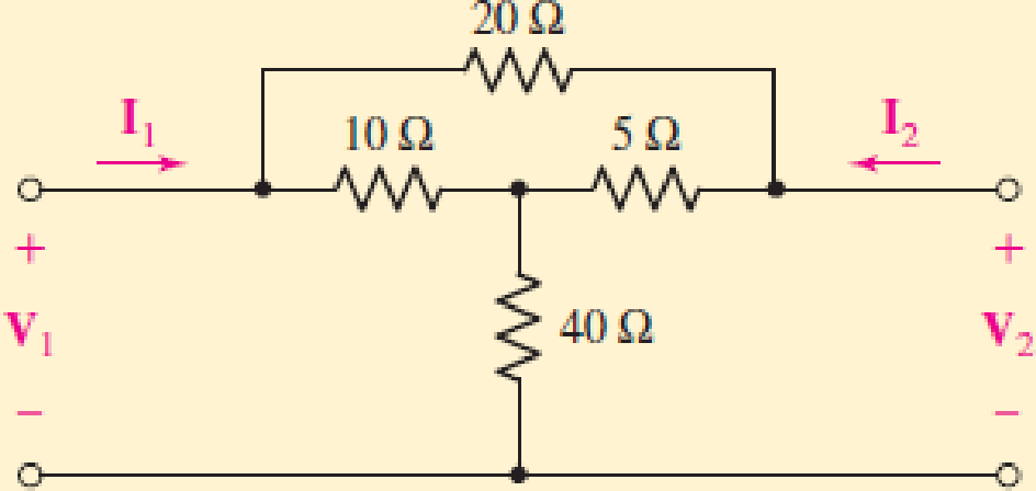
Chapter 16.2, Problem 3P
By applying the appropriate 1 V sources and short circuits to the circuit shown in Fig. 16.10, find (a) y11; (b) y21; (c) y22; (d) y12.
Expert Solution & Answer
Want to see the full answer?
Check out a sample textbook solution
Students have asked these similar questions
2) Design the circuit shown in Figure 2 to provide bias current of IQ2= 150 uA.
Assume circuit parameters of IREF2 = 250 UA, V+ = 3 V, and V = -3 V. The
transistor parameters are VTP = -0.6 V, λ = 0, K'p= 40 uA/V², W/Lc = 15 and
W/LA = 25.
V+
Mc
+
VSGC VSGB
+
MB
VSGA
+
+
MA VSDA
IREF2
V-
Figure 2
ww
RD=8kQ
٣/١
a
い
يكا
+91- PU + 96852
A. For the RL-circuit with i(0)=0, Find the current i(t) using LT
R=2
V(t)=sin3t
L=1H
B. Find Invers Laplace Transform for Z(s) =
=
220125
750 x2.01
4s2 +2s+3
s2-3s+2
1) Taking base current into account, determine the value of I copy in each circuit depicted in Fig
1. Normalize the error to nominal value of Icopy.
REF
Vcc
AE
Vcc
QREF
Figure 1- a
I copy
5AE
REF
12
Q₁
copy
Q2
5AE
2AE
ЗАЕ
QREF
Figure 1-b
Chapter 16 Solutions
Loose Leaf for Engineering Circuit Analysis Format: Loose-leaf
Ch. 16.1 - Find the input impedance of the network shown in...Ch. 16.1 - Write a set of nodal equations for the circuit of...Ch. 16.2 - By applying the appropriate 1 V sources and short...Ch. 16.2 - Prob. 4PCh. 16.2 - Prob. 5PCh. 16.3 - Prob. 6PCh. 16.3 - Use Y and Y transformations to determine Rin for...Ch. 16.4 - Find z for the two-port shown in (a) Fig. 16.23a;...Ch. 16.4 - Prob. 9PCh. 16.5 - Prob. 10P
Ch. 16.5 - Prob. 11PCh. 16.6 - Prob. 12PCh. 16 - For the following system of equations, (a) write...Ch. 16 - With regard to the passive network depicted in...Ch. 16 - Determine the input impedance of the network shown...Ch. 16 - For the one-port network represented schematically...Ch. 16 - Prob. 6ECh. 16 - Prob. 7ECh. 16 - Prob. 8ECh. 16 - Prob. 9ECh. 16 - (a) If both the op amps shown in the circuit of...Ch. 16 - Prob. 11ECh. 16 - Prob. 12ECh. 16 - Prob. 13ECh. 16 - Prob. 14ECh. 16 - Prob. 15ECh. 16 - Prob. 16ECh. 16 - Prob. 17ECh. 16 - Prob. 18ECh. 16 - Prob. 19ECh. 16 - Prob. 20ECh. 16 - For the two-port displayed in Fig. 16.49, (a)...Ch. 16 - Prob. 22ECh. 16 - Determine the input impedance Zin of the one-port...Ch. 16 - Determine the input impedance Zin of the one-port...Ch. 16 - Employ Y conversion techniques as appropriate to...Ch. 16 - Prob. 26ECh. 16 - Prob. 27ECh. 16 - Prob. 28ECh. 16 - Compute the three parameter values necessary to...Ch. 16 - It is possible to construct an alternative...Ch. 16 - Prob. 31ECh. 16 - Prob. 32ECh. 16 - Prob. 33ECh. 16 - Prob. 34ECh. 16 - The two-port networks of Fig. 16.50 are connected...Ch. 16 - Prob. 36ECh. 16 - Prob. 37ECh. 16 - Obtain both the impedance and admittance...Ch. 16 - Prob. 39ECh. 16 - Determine the h parameters which describe the...Ch. 16 - Prob. 41ECh. 16 - Prob. 42ECh. 16 - Prob. 43ECh. 16 - Prob. 44ECh. 16 - Prob. 45ECh. 16 - Prob. 46ECh. 16 - Prob. 47ECh. 16 - Prob. 48ECh. 16 - Prob. 49ECh. 16 - Prob. 50ECh. 16 - (a) Employ suitably written mesh equations to...Ch. 16 - Prob. 52ECh. 16 - Prob. 53ECh. 16 - The two-port of Fig. 16.65 can be viewed as three...Ch. 16 - Consider the two separate two-ports of Fig. 16.61....Ch. 16 - Prob. 56ECh. 16 - Prob. 57ECh. 16 - Prob. 58ECh. 16 - (a) Obtain y, z, h, and t parameters for the...Ch. 16 - Four networks, each identical to the one depicted...Ch. 16 - A cascaded 12-element network is formed using four...Ch. 16 - Prob. 62ECh. 16 - Continuing from Exercise 62, the behavior of a ray...
Additional Engineering Textbook Solutions
Find more solutions based on key concepts
Comprehension Check 7-14
The power absorbed by a resistor can be given by P = I2R, where P is power in units of...
Thinking Like an Engineer: An Active Learning Approach (4th Edition)
The solid steel shaft AC has a diameter of 25 mm and is supported by smooth bearings at D and E. It is coupled ...
Mechanics of Materials (10th Edition)
What is an uninitialized variable?
Starting Out with Programming Logic and Design (5th Edition) (What's New in Computer Science)
The job of the _____ is to fetch instructions, carry out the operations commanded by the instructions, and prod...
Starting Out With Visual Basic (8th Edition)
What types of coolant are used in vehicles?
Automotive Technology: Principles, Diagnosis, And Service (6th Edition) (halderman Automotive Series)
Knowledge Booster


Learn more about
Need a deep-dive on the concept behind this application? Look no further. Learn more about this topic, electrical-engineering and related others by exploring similar questions and additional content below.Similar questions
- 12.2 Evaluate each of the following integrals. (a) G₁: = = √ (31³ +21² + 1) [8(t) +48 (t − 2)] dt -21 (b) G₂ = G2 = 4(e¯2ª +1)[☎(t) −28(t − 2)] dt -2 -20 (c) G3 = 0 3( cos 2π- 1) [8(t) +☎(t − 10)] dt -20arrow_forward3) The differential amplifier in Figure 3 is biased with a three-transistor current source. The transistor parameters are ẞ= 100, VBE (on) = 0.7 V, and VA = ∞. a) Determine I1. Ic2, IC4, VCE2, and VCE4. b) Determine a new value of R1 such that VCE4 = 2.5V. what are the values of Ic4, Ic2, I1, and R₁? +5 V Q1 R₁ = 8.5 ΚΩ IC4 23 RC= • 2 ΚΩ + 24 VCE4 RC= 2 ΚΩ est Ic2 + Q2 VCE2 -5 V Figure 3arrow_forward12.1 Evaluate each of the following integrals: (a) G₁ = √(33-4t²+3)[8(t) +28(t − 2)] dt. (b) G₂ = √442(e³ +1)[8(t) − 28(t − 2)] dt. .16 -31 (c) G3=124t sin(2лt) − 1][§(t − 1) +☎(t − 6)] dt.arrow_forward
- Why is the voltage drop of a self-excited generator greater than the voltagedrop of a separately excited generator?arrow_forwardWhen driving a DC shunt generator with a synchronous prime mover motor, why does the AC amperage to the synchronous motor machine increase as load is added to the generator?arrow_forward100 What is the phase and gain margins of the following system, is it stable or not. Design a PI controller for the following unstable process if any. 50 -120 -130 0 -140 -50 -150 -100 -160 <<-150 -170 -200 -180 10-1 10° 10¹ 102 103 104 105 1071 10° 10¹ 102 103 101 105 Frequency (rad/s) Frequency (rad/s)arrow_forward
- Please assist in the below questionarrow_forwardA. For the RL-circuit with i(0)=0, Find the current i(t) using LT R=2 Ω V(t)=sin3t B. Find Invers Laplace Transform for Z(s) L= 1H 4s2 +2s+3 = s2-3s+2arrow_forwardGiven the circuit diagram in. Find the following voltages: Vda, Vbh, Vgc, Vdi, Vfa, Vac, Vai, Vhf, Vfb, and Vdc.arrow_forward
- L ✓ 30 UF 2mtt The voltage applied across 3-branched circuit of figure 2 is given by v = 100 sin(5000t+ π/4). Calculate the branch currents and total current. v 25ŹR 00arrow_forward10 mA 2 ΚΩ 2 ΚΩ 6 ΚΩ x + ww 4 ΚΩ 4 ΚΩ +1 2 Varrow_forwardFind Vx,V1,V3,V0 according to the case of the circuits using KVLarrow_forward
arrow_back_ios
SEE MORE QUESTIONS
arrow_forward_ios
Recommended textbooks for you
 Introductory Circuit Analysis (13th Edition)Electrical EngineeringISBN:9780133923605Author:Robert L. BoylestadPublisher:PEARSON
 Delmar's Standard Textbook Of ElectricityElectrical EngineeringISBN:9781337900348Author:Stephen L. HermanPublisher:Cengage Learning
 Programmable Logic ControllersElectrical EngineeringISBN:9780073373843Author:Frank D. PetruzellaPublisher:McGraw-Hill Education
 Fundamentals of Electric CircuitsElectrical EngineeringISBN:9780078028229Author:Charles K Alexander, Matthew SadikuPublisher:McGraw-Hill Education
 Electric Circuits. (11th Edition)Electrical EngineeringISBN:9780134746968Author:James W. Nilsson, Susan RiedelPublisher:PEARSON
 Engineering ElectromagneticsElectrical EngineeringISBN:9780078028151Author:Hayt, William H. (william Hart), Jr, BUCK, John A.Publisher:Mcgraw-hill Education,
Introductory Circuit Analysis (13th Edition)
Electrical Engineering
ISBN:9780133923605
Author:Robert L. Boylestad
Publisher:PEARSON
Delmar's Standard Textbook Of Electricity
Electrical Engineering
ISBN:9781337900348
Author:Stephen L. Herman
Publisher:Cengage Learning
Programmable Logic Controllers
Electrical Engineering
ISBN:9780073373843
Author:Frank D. Petruzella
Publisher:McGraw-Hill Education
Fundamentals of Electric Circuits
Electrical Engineering
ISBN:9780078028229
Author:Charles K Alexander, Matthew Sadiku
Publisher:McGraw-Hill Education
Electric Circuits. (11th Edition)
Electrical Engineering
ISBN:9780134746968
Author:James W. Nilsson, Susan Riedel
Publisher:PEARSON
Engineering Electromagnetics
Electrical Engineering
ISBN:9780078028151
Author:Hayt, William H. (william Hart), Jr, BUCK, John A.
Publisher:Mcgraw-hill Education,
L21E127 Control Systems Lecture 21 Exercise 127: State-space model of an electric circuit; Author: bioMechatronics Lab;https://www.youtube.com/watch?v=sL0LtyfNYkM;License: Standard Youtube License