
Concept explainers
Videos
Two rotating rods in the vertical plane are connected by a slider block P of negligible mass. The rod attached at A has a weight of 1.6 lb and a length of 8 in. Rod BP weighs 2 lb and is 10 in. long and the friction between block P and AE is negligible. The motion of the system is controlled by a couple M applied to rod BP. Knowing that rod BP has a constant angular velocity of 20 rad/s clockwise, determine (a) the couple M, (b) the components of the force exerted on AE by block P.
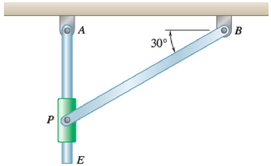
Fig. P16.141 and Fig. P16.142
(a)
Find the value of couple M.
Answer to Problem 16.141P
The value of couple M is
Explanation of Solution
Given information:
The weight of the rod AE is
The weight of the rod BP is
The length of the rod AE is
The length of the rod BP is
The angular velocity is
Calculation:
Consider the acceleration due to gravity as
Calculate the position vector
The position of P with respect to A.
The position of P with respect to B.
The position of P with respect to E.
The angular velocity of rod BP in vector form is
Calculate the velocity of rod BP
Substitute
Consider the relative angular velocity of rod AE as
Calculate the velocity of point P
Substitute
Resolving i and j components as shown below.
Calculate the acceleration of rod BP
Substitute 0 for
Calculate the acceleration of point P with respect to point E
Substitute
Calculate the acceleration of point P
Substitute
Resolving i and j components as shown below.
Calculate the mass of
For rod AE.
Substitute
For rod BP.
Substitute
Calculate the mass moment of inertia
For rod AE.
Substitute
For rod BP.
Substitute
Calculate the position vector
The position of mass center G with respect to the rod AE.
The position of mass center H with respect to the rod BP.
Calculate the acceleration of point G
Substitute
Calculate the acceleration of point H
Substitute 0 for
Calculate the inertial terms of the mass center
For rod AE.
For rod BP.
Calculate the effective couples at mass center
For rod AE.
For rod BP.
Sketch the Free Body Diagram of rod AE as shown in Figure 1.
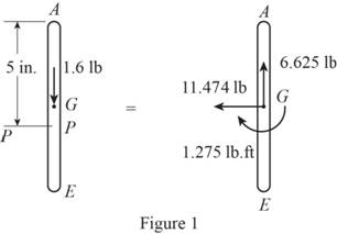
Refer to Figure 1.
Apply the Equilibrium of moment about A as shown below.
Substitute
Sketch the Free Body Diagram of rod BP as shown in Figure 2.
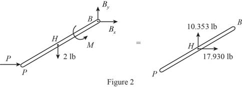
Refer to Figure 2.
Apply the Equilibrium of moment about A as shown below.
Substitute
Hence, the couple M is
(b)
The components of the force exerted on AE by block.
Answer to Problem 16.141P
The components of the force exerted on AE by block is
Explanation of Solution
Given information:
The weight of the rod AE is
The weight of the rod BP is
The length of the rod AE is
The length of the rod BP is
The angular velocity is
Calculation:
Refer to part (a).
The components of the force exerted on AE by block
Therefore, the components of the force exerted on AE by block is
Want to see more full solutions like this?
Chapter 16 Solutions
Vector Mechanics for Engineers: Statics and Dynamics
Additional Engineering Textbook Solutions
Vector Mechanics For Engineers
Electric Circuits. (11th Edition)
Thermodynamics: An Engineering Approach
Modern Database Management
Starting Out with C++ from Control Structures to Objects (9th Edition)
Management Information Systems: Managing The Digital Firm (16th Edition)


- Draw left view of the first orthographic projectionarrow_forwardSketch and Describe a timing diagram for a 2 stroke diesel engine emphasis on the 2 stroke as my last answer explained 4 stroke please include a diagram or sketch.arrow_forwardA 4 ft 200 Ib 1000 Ib.ft C 2 ft 350 Ib - за в 2.5 ft 150 Ib 250 Ib 375 300 Ib Replace the force system acting on the frame. shown in the figure by a resultant force (magnitude and direction), and specify where its line of action intersects member (AB), measured from point (A).arrow_forward
- A continuous flow calorimeter was used to obtain the calorific value of a sample of fuel and the following data collected: Mass of fuel: 2.25 kgInlet water temperature: 11 ° COutlet water temperature 60 ° CQuantity of water: 360 Liters Calorimeter efficiency: 85%Calculate the calorific value of the sample ( kJ / kg ). ive submitted this question twice and have gotten two way different answers. looking for some help thanksarrow_forward15 kg of steel ball bearings at 100 ° C is immersed in 25 kg of water at 20 ° C . Assuming no loss of heat to or from the container, calculate the final temperature of the water after equilibrium has been attained.Specific heat of steel: 0.4857 kJ / kg / ° KSpecific heat of water: 4.187 kJ / kg / ° Karrow_forwardSketch and explain a PV Diagram and a Temperature Entropy Diagram for a 4 stroke diesel enginearrow_forward
- A continuous flow calorimeter was used to obtain the calorific value of a sample of fuel and the following data collected: Mass of fuel: 2.25 kgInlet water temperature: 11 ° COutlet water temperature 60 ° CQuantity of water: 360 Liters Calorimeter efficiency: 85%Calculate the calorific value of the sample ( kJ / kg ).arrow_forwardChapter 12 - Lecture Notes.pptx: (MAE 272-01) (SP25) DY... Scoresarrow_forwardmylabmastering.pearson.com Chapter 12 - Lecture Notes.pptx: (MAE 272-01) (SP25) DY... P Pearson MyLab and Mastering Scoresarrow_forwardanswer the fallowing Brake Specific Fuel Consumption - 0.3 kg/kwh, Mechanical Efficiency- 90% Calorific Value of Fuel -45 MJ/kg. Given these values, find the indicated power, indicated thermal efficiency and brake thermal efficiencyarrow_forwardProblem 6. The circular plate shown rotates about its vertical diameter. At the instant shown, the angular velocity ₁ of the plate is 10 rad/s and is decreasing at the rate of 25 rad/s². The disk lies in the XY plane and Point D of strap CD moves upward. The relative speed u of Point D of strap CD is 1.5 m/s and is decreasing at the rate of 3 m/s². Determine (a) the velocity of D, (b) the acceleration of D. Answers: =0.75 +1.299]-1.732k m/s a=-28.6 +3.03-10.67k m/s² 200 mm x Zarrow_forwardProblem 1. The flywheel A has an angular velocity o 5 rad/s. Link AB is connected via ball and socket joints to the flywheel at A and a slider at B. Find the angular velocity of link AB and the velocity of slider B at this instant. (Partial Answer: @ABN = -2î + 2.25; red Z -1.2 ft C -7 Y -1.5 ft- B 2.0 ftarrow_forwardarrow_back_iosSEE MORE QUESTIONSarrow_forward_iosRecommended textbooks for you
 Elements Of ElectromagneticsMechanical EngineeringISBN:9780190698614Author:Sadiku, Matthew N. O.Publisher:Oxford University Press
 Mechanics of Materials (10th Edition)Mechanical EngineeringISBN:9780134319650Author:Russell C. HibbelerPublisher:PEARSON
 Thermodynamics: An Engineering ApproachMechanical EngineeringISBN:9781259822674Author:Yunus A. Cengel Dr., Michael A. BolesPublisher:McGraw-Hill Education
 Control Systems EngineeringMechanical EngineeringISBN:9781118170519Author:Norman S. NisePublisher:WILEY
 Mechanics of Materials (MindTap Course List)Mechanical EngineeringISBN:9781337093347Author:Barry J. Goodno, James M. GerePublisher:Cengage Learning
 Engineering Mechanics: StaticsMechanical EngineeringISBN:9781118807330Author:James L. Meriam, L. G. Kraige, J. N. BoltonPublisher:WILEY
Elements Of ElectromagneticsMechanical EngineeringISBN:9780190698614Author:Sadiku, Matthew N. O.Publisher:Oxford University PressMechanics of Materials (10th Edition)Mechanical EngineeringISBN:9780134319650Author:Russell C. HibbelerPublisher:PEARSONThermodynamics: An Engineering ApproachMechanical EngineeringISBN:9781259822674Author:Yunus A. Cengel Dr., Michael A. BolesPublisher:McGraw-Hill EducationControl Systems EngineeringMechanical EngineeringISBN:9781118170519Author:Norman S. NisePublisher:WILEYMechanics of Materials (MindTap Course List)Mechanical EngineeringISBN:9781337093347Author:Barry J. Goodno, James M. GerePublisher:Cengage LearningEngineering Mechanics: StaticsMechanical EngineeringISBN:9781118807330Author:James L. Meriam, L. G. Kraige, J. N. BoltonPublisher:WILEY