
Concept explainers
Videos
(a)
Find the angular acceleration of each cylinder
(a)
Answer to Problem 16.45P
The angular acceleration of each cylinder
Explanation of Solution
The weight of the cylinder A
The weight of the cylinder B
The weight of the cylinder C
The initial angular velocity of the cylinder A
The coefficient of the kinetic friction
The radius of the cylinder A
The radius of the cylinder B
The radius of the cylinder C
Calculation:
Consider the acceleration due to gravity (g) as
Convert the unit of the radius of the cylinder A
Convert the unit of the radius of the cylinder B
Convert the unit of the radius of the cylinder C
Calculate the mass of the cylinder A
Substitute
Calculate the mass of the cylinder B
Substitute
Calculate the mass of the cylinder C
Substitute
Calculate the mass moment of inertia of the cylinder A
Substitute
Calculate the mass moment of inertia of the cylinder B
Substitute
Calculate the mass moment of inertia of the cylinder C
Substitute
Calculate the tangential acceleration of contact point between cylinder B and C
Here,
The friction force at the contact point between cylinder A and C
Show the free body diagram of the cylinder B as in Figure 1.
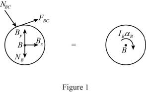
Here,
Refer to Figure 1.
Calculate the moment about point B by applying the equation of equilibrium:
Substitute
Show the free body diagram of the cylinder C as in Figure 2.
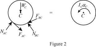
Here,
Refer to Figure 2.
Calculate the moment about point C by applying the equation of equilibrium:
Substitute
Calculate the normal force at the contact point between cylinder A and C
Substitute
Consider that the contact point between cylinder A and C is P.
Calculate the components of forces acting along the line CP:
Calculate the angular acceleration of the cylinder C
Substitute
Calculate the friction force at the contact point between cylinder A and C
Substitute
Calculate the friction force at the contact point between cylinder B and C
Substitute
Calculate the normal force at the contact point between cylinder A and C
Substitute
Show the free body diagram of the cylinder A as in Figure 3.
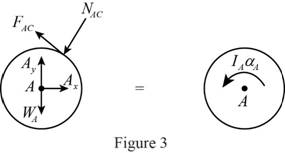
Here,
Refer to Figure 3.
Consider that the contact point between cylinder B and C is Q.
Calculate the components of forces acting along the line CQ:
Calculate the normal force at the contact point between cylinder B and C
Substitute
Calculate the angular acceleration of the cylinder A
Calculate the moment about point A by applying the equation of equilibrium:
Substitute
Calculate the angular acceleration of the cylinder A
Substitute
Hence, the angular acceleration of each cylinder
(b)
Find the final angular velocity of each disk
(b)
Answer to Problem 16.45P
The final angular velocity of each disk
Explanation of Solution
The weight of the cylinder A
The weight of the cylinder B
The weight of the cylinder C
The initial angular velocity of the cylinder A
The coefficient of the kinetic friction
The radius of the cylinder A
The radius of the cylinder B
The radius of the cylinder C
Calculation:
Refer to part (a).
The convert the unit of the initial angular velocity of the disk A
Calculate the angular velocity of cylinder A
Substitute
Calculate the tangential velocity of cylinder A
Substitute
Calculate the angular velocity of cylinder C
Substitute
Calculate the tangential velocity of cylinder C
Substitute
Calculate the time taken when tangential velocities are equal:
Substitute
Calculate the final angular velocity of the disk A
Substitute
Calculate the final angular velocity of the disk C
Substitute
Calculate the final angular velocity of the disk B
Substitute
Hence, the final angular velocity of each disk
Want to see more full solutions like this?
Chapter 16 Solutions
Vector Mechanics for Engineers: Statics and Dynamics


- (read image)arrow_forward(read image) Answer Providedarrow_forwardThis is part B Part A's question and answer was find moment of inertia (Ix = 3.90×10^5) and radius of gyration (kx = 21.861) Determine the centroid ( x & y ) of the I-section, Calculate the moment of inertia of the section about itscentroidal x & y axes. How or why is this result different fromthe result of a previous problem?arrow_forward
- Determine by direct integration the moment of inertia of theshaded area of figure with respect to the y axis shownarrow_forwardConsider the feedback controlled blending system shown below, which is designed to keep theoutlet concentration constant despite potential variations in the stream 1 composition. The density of all streamsis 920 kg/m3. At the nominal steady state, the flow rates of streams 1 and 2 are 950 and 425 kg/min,respectively, the liquid level in the tank is 1.3 m, the incoming mass fractions are x1 = 0.27, x2 = 0.54. Noticethe overflow line, indicating that the liquid level remains constant (i.e. any change in total inlet flow ratetranslates immediately to the same change in the outlet flow rate). You may assume the stream 1 flowrate andthe stream 2 composition are both constant. Use minutes as the time unit throughout this problem. Identify any controlled variable(s) (CVs), manipulated variable(s) (MVs),and disturbance variable(s) (DVs) in this problem. For each, explain how you know that’show it is classified.CVs: ___________, MVs: _____________, DVs: ______________ b) Draw a block diagram…arrow_forwardA heat transfer experiment is conducted on two identical spheres which are initially at the same temperature. The spheres are cooled by placing them in a channel. The fluid velocity in the channel is non-uniform, having a profile as shown. Which sphere cools off more rapidly? Explain. V 1arrow_forward
- My ID# 016948724 last 2 ID# 24 Last 3 ID# 724 Please help to find the correct answer for this problem using my ID# first write le line of action and then help me to find the forces {fx= , fy= mz= and for the last find the moment of inertial about the show x and y axes please show how to solve step by steparrow_forwardMy ID# 016948724 last 2 ID# 24 Last 3 ID# 724 Please help to find the correct answer for this problem using my ID# first write le line of action and then help me to find the forces and the tension {fx= , fy= mz=arrow_forwardMy ID# 016948724 last 2 ID# 24 Last 3 ID# 724 Please help to find the correct answer for this problem using my ID# first write le line of action and then help me to find the forces {fx= , fy= mz=arrow_forward
- my ID is 016948724 Last 2 ID# 24 Last 3 ID# 724 please help me to solve this problem step by step show me how to solve first wirte the line actions and then find the forces {fx=, fy=, mz= and for the last step find the support reactions and find forcesarrow_forwardUppgift 1 (9p) 3 m 3 m 3 m 3 m H G F 3 m ↑ Dy D B AAY 30° 8 kN Ay Fackverket i figuren ovan är belastat med en punktlast. Bestäm normalkraften i stängerna BC, BG och FG.arrow_forwardThe cardiovascular countercurrent heat exchnager mechanism is to warm venous blood from 28 degrees C to 35 degrees C at a mass flow rate of 2 g/s. The artery inflow temp is 37 degrees C at a mass flow rate of 5 g/s. The average diameter of the vein is 5 cm and the overall heat transfer coefficient is 125 W/m^2*K. Determine the overall blood vessel length needed too warm the venous blood to 35 degrees C if the specific heat of both arterial and venous blood is constant and equal to 3475 J/kg*K.arrow_forward
 Elements Of ElectromagneticsMechanical EngineeringISBN:9780190698614Author:Sadiku, Matthew N. O.Publisher:Oxford University Press
 Mechanics of Materials (10th Edition)Mechanical EngineeringISBN:9780134319650Author:Russell C. HibbelerPublisher:PEARSON
 Thermodynamics: An Engineering ApproachMechanical EngineeringISBN:9781259822674Author:Yunus A. Cengel Dr., Michael A. BolesPublisher:McGraw-Hill Education
 Control Systems EngineeringMechanical EngineeringISBN:9781118170519Author:Norman S. NisePublisher:WILEY
 Mechanics of Materials (MindTap Course List)Mechanical EngineeringISBN:9781337093347Author:Barry J. Goodno, James M. GerePublisher:Cengage Learning
 Engineering Mechanics: StaticsMechanical EngineeringISBN:9781118807330Author:James L. Meriam, L. G. Kraige, J. N. BoltonPublisher:WILEY