
EE 98: Fundamentals of Electrical Circuits - With Connect Access
6th Edition
ISBN: 9781259981807
Author: Alexander
Publisher: MCG
expand_more
expand_more
format_list_bulleted
Videos
Textbook Question
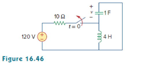
Chapter 16, Problem 23P
Obtain v (t) for t > 0 in the circuit of Fig. 16.46.
Expert Solution & Answer
Want to see the full answer?
Check out a sample textbook solution
Students have asked these similar questions
Don't use ai to answer I will report you answer
8-1) similar to Lathi & Ding, Prob. P.5.1-2
The figure below shows the Fourier spectra of signals of g,(t) and g₁(t). Determine the Nyquist rate and
the corresponding sampling interval for signals of g,(t), g,(t), g₁(1) - g¸(1), g¸³(t), and g₁(1)g₁(1).
Hint: Use the frequency convolution and the width property of convolution.
G₁(f)
G₂(f)
-8000
0 8000 f
-20000
10
20000 f
• We will use the Wattmeter to find the average power supplied/absorbed by each component.
The following figure shows how to connect the Wattmeter to measure the average power
absorbed by the resistor. Note that the Wattmeter consists of a Voltmeter and an Ammeter. The
Voltmeter must be connected in parallel with the component and the Ammeter must be connected
in series with the component. You must pay attention to the polarity of the voltage across the
component as well as the direction of the current flowing through the component.
5Vpk
1kHz
30°
ww
40
Z=A-JB
Wattmeter-XWM1
2.503 W
Power factor:
1.00000
Voltage
Current
•
•
Similarly connect a second Wattmeter to measure the average power supplied by the source.
Connect a third Wattmeter to measure the average power in the capacitor. Does this value agree
with the theoretical value?
Perform Interactive Simulation under Analysis and Simulation. Double click on Wattmeters to
see the average power values. Note that the Wattmeter also…
Chapter 16 Solutions
EE 98: Fundamentals of Electrical Circuits - With Connect Access
Ch. 16.2 - Determine vo(t) in the circuit of Fig. 16.6,...Ch. 16.2 - Prob. 2PPCh. 16.2 - Prob. 3PPCh. 16.3 - For the circuit shown in Fig. 16.12 with the same...Ch. 16.3 - Prob. 5PPCh. 16.3 - The initial energy in the circuit of Fig. 16.17 is...Ch. 16.4 - Prob. 7PPCh. 16.4 - Prob. 8PPCh. 16.4 - Prob. 9PPCh. 16.5 - Obtain the state variable model for the circuit...
Ch. 16.5 - Prob. 11PPCh. 16.5 - Prob. 12PPCh. 16.6 - For what value of is the circuit in Fig. 16.29...Ch. 16.6 - Prob. 14PPCh. 16.6 - Prob. 15PPCh. 16.6 - Synthesize the function Vo(s)Vin=2ss2+6s+10 using...Ch. 16 - Prob. 1RQCh. 16 - The current through an RL series circuit with...Ch. 16 - Prob. 3RQCh. 16 - Prob. 4RQCh. 16 - Prob. 5RQCh. 16 - Prob. 6RQCh. 16 - Prob. 7RQCh. 16 - Prob. 8RQCh. 16 - Prob. 9RQCh. 16 - Prob. 10RQCh. 16 - The current in an RLC circuit is described by...Ch. 16 - The differential equation that describes the...Ch. 16 - Prob. 3PCh. 16 - If R = 20 , L = 0.6 H, what value of C will make...Ch. 16 - The responses of a series RLC circuit are vc(t) =...Ch. 16 - Prob. 6PCh. 16 - Prob. 7PCh. 16 - Prob. 8PCh. 16 - Prob. 9PCh. 16 - The step responses of a series RLC circuit are Vc...Ch. 16 - The step response of a parallel RLC circuit is v =...Ch. 16 - Prob. 12PCh. 16 - Prob. 13PCh. 16 - Prob. 14PCh. 16 - For the circuit in Fig. 16.38. calculate the value...Ch. 16 - The capacitor in the circuit of Fig. 16.39 is...Ch. 16 - If is(t) = 7.5e2t u(t) A in the circuit shown in...Ch. 16 - Find v(t), t 0 in the circuit of Fig. 16.41. Let...Ch. 16 - The switch in Fig. 16.42 moves from position A to...Ch. 16 - Find i(t) for t 0 in the circuit of Fig. 16.43.Ch. 16 - In the circuit of Fig. 16.44, the switch moves...Ch. 16 - Find the voltage across the capacitor as a...Ch. 16 - Obtain v (t) for t 0 in the circuit of Fig....Ch. 16 - The switch in the circuit of Fig. 16.47 has been...Ch. 16 - Calculate v(t) for t 0 in the circuit of Fig....Ch. 16 - Prob. 26PCh. 16 - Find v (t) for t 0 in the circuit in Fig. 16.50.Ch. 16 - For the circuit in Fig. 16.51, find v(t) for t 0.Ch. 16 - Prob. 29PCh. 16 - Find vo(t), for all t 0, in the circuit of Fig....Ch. 16 - Prob. 31PCh. 16 - For the network in Fig. 16.55, solve for i(t) for...Ch. 16 - Using Fig. 16.56, design a problem to help other...Ch. 16 - Prob. 34PCh. 16 - Prob. 35PCh. 16 - Prob. 36PCh. 16 - Prob. 37PCh. 16 - The switch in the circuit of Fig. 16.61 is moved...Ch. 16 - Prob. 39PCh. 16 - Prob. 40PCh. 16 - Prob. 41PCh. 16 - Prob. 42PCh. 16 - Prob. 43PCh. 16 - Prob. 44PCh. 16 - Find v(t) for t 0 in the circuit in Fig. 16.68.Ch. 16 - Prob. 46PCh. 16 - Determine io(t) in the network shown in Fig....Ch. 16 - Prob. 48PCh. 16 - Find i0(t) for t 0 in the circuit in Fig. 16.72....Ch. 16 - Prob. 50PCh. 16 - In the circuit of Fig. 16.74, find i(t) for t 0.Ch. 16 - Prob. 52PCh. 16 - In the circuit of Fig. 16.76, the switch has been...Ch. 16 - Prob. 54PCh. 16 - Prob. 55PCh. 16 - Calculate io(t) for t 0 in the network of Fig....Ch. 16 - Prob. 57PCh. 16 - Prob. 58PCh. 16 - Find vo(t) in the circuit of Fig. 16.82 if vx(0) =...Ch. 16 - Prob. 60PCh. 16 - Prob. 61PCh. 16 - Using Fig. 16.85, design a problem to help other...Ch. 16 - Consider the parallel RLC circuit of Fig. 16.86....Ch. 16 - The switch in Fig. 16.87 moves from position 1 to...Ch. 16 - For the RLC circuit shown in Fig. 16.88, find the...Ch. 16 - For the op amp circuit in Fig. 16.89, find v0(t)...Ch. 16 - Given the op amp circuit in Fig. 16.90, if v1(0+)...Ch. 16 - Prob. 68PCh. 16 - Prob. 69PCh. 16 - Using Fig. 16.93, design a problem to help other...Ch. 16 - Prob. 71PCh. 16 - The transfer function of a system is H(s)=s23s+1...Ch. 16 - Prob. 73PCh. 16 - Design a problem to help other students better...Ch. 16 - Prob. 75PCh. 16 - For the circuit in Fig. 16.95, find H(s) =...Ch. 16 - Obtain the transfer function H(s) = VoVs for the...Ch. 16 - Prob. 78PCh. 16 - For the circuit in Fig. 16.97, find: (a) I1/Vs (b)...Ch. 16 - Refer to the network in Fig. 16.98. Find the...Ch. 16 - Prob. 81PCh. 16 - Prob. 82PCh. 16 - Refer to the RL circuit in Fig. 16.101. Find: (a)...Ch. 16 - A parallel RL circuit has R = 4 and L = 1 H. The...Ch. 16 - Prob. 85PCh. 16 - Prob. 86PCh. 16 - Prob. 87PCh. 16 - Prob. 88PCh. 16 - Develop the state equations for the circuit shown...Ch. 16 - Prob. 90PCh. 16 - Prob. 91PCh. 16 - Prob. 92PCh. 16 - Prob. 93PCh. 16 - Prob. 94PCh. 16 - Prob. 95PCh. 16 - Prob. 96PCh. 16 - A system is formed by cascading two systems as...Ch. 16 - Determine whether the op amp circuit in Fig....Ch. 16 - It is desired realize the transfer function...Ch. 16 - Prob. 100PCh. 16 - Prob. 101PCh. 16 - Synthesize the transfer function...Ch. 16 - Prob. 103CPCh. 16 - Prob. 104CPCh. 16 - Prob. 105CP
Knowledge Booster


Learn more about
Need a deep-dive on the concept behind this application? Look no further. Learn more about this topic, electrical-engineering and related others by exploring similar questions and additional content below.Similar questions
- • We will use the Wattmeter to find the average power supplied/absorbed by each component. The following figure shows how to connect the Wattmeter to measure the average power absorbed by the resistor. Note that the Wattmeter consists of a Voltmeter and an Ammeter. The Voltmeter must be connected in parallel with the component and the Ammeter must be connected in series with the component. You must pay attention to the polarity of the voltage across the component as well as the direction of the current flowing through the component. 5Vpk 1kHz 30° ww 40 Z=A-JB Wattmeter-XWM1 2.503 W Power factor: 1.00000 Voltage Current • • Similarly connect a second Wattmeter to measure the average power supplied by the source. Connect a third Wattmeter to measure the average power in the capacitor. Does this value agree with the theoretical value? Perform Interactive Simulation under Analysis and Simulation. Double click on Wattmeters to see the average power values. Note that the Wattmeter also…arrow_forward8-3) Bandpass sampling A bandpass signal is confined to the frequency range from 7.5 to 10.5 kHz. Find the allowed ranges of the sampling rate for this signal. Sketch the amplitude spectrum of a hypothetical message, the amplitude spectrum of the sampled signal, and the transfer function of a suitable recovery filter if the sampling rate is chosen in the center of the lowest range available.arrow_forward8-4) Similar to Lathi & Ding, Prob. P.5.1-5 6.1-4 A low-pass signal g(t) sampled at rate of fs > 2B needs reconstruction. The sampling interval is Ts = 1/fs. (a) If the reconstruction pulse used is p(1) = [1 - specify the equalizer filter E(f) to recover g (1). (b) If the reconstruction pulse used is p(t) = П Ts/2 specify the equalizer filter E(f) to recover g (1).arrow_forward
- 8-2) Lathi & Ding, Prob. P.5.1-1 Determine the Nyquist sampling rate for the following signals, explaining your method: (a) 4 sinc(420лt); (b) 5sinc² (6500лt); (c) sinc(1800лt)+ sinc² (2000лt); (d) 2 sinc(500лt) sin(300л)arrow_forward2) A load consisting of a 1350 Q2 resistor in parallel with a 405 mH inductor is connected across the terminals of a sinusoidal voltage source Vg, where Vg = 90 cos(2500t) V. Find a) the average power delivered to the load, b) the reactive power for the load, c) the apparent power for the load, and d) the power factor of the load.arrow_forward4) Find the phasor voltage Vs for the following circuit if loads L1 and L2 are absorbing 15 kVA at 0.6 pf lagging and 6 kVA at 0.8 pf leading, respectively. Express Vs in polar form. + j10 + 200/0° V(rms) | L1 Li L2arrow_forward
- 3) A 100-V rms, 60 Hz source is applied to a load impedance Z. The apparent power entering the load is 120 VA at a power factor of 0.707 lagging. a) Calculate the complex power b) Find the rms current supplied to the load c) Determine Z d) Assuming that Z = R + jwL, find the values of R and L.arrow_forward1) Find the average power delivered by the ideal current source in the following circuit if ig = 30 cos(25000t) mA. 202 w 50 w 40 με 40 pHarrow_forwardAnswer question 3 using Multisim pleasearrow_forward
- Answer question 2 using Multisim pleasearrow_forwardQ1. Choose the correct answer 1. With fixed number of quantization levels in PCM, the quantization noise is (linearly proportional to signal amplitude, non-linearly proportional to signal amplitude, linearly proportional to signal frequency, non-linearly proportional to signal frequency). 2. A PCM encoder uses 130 quantization levels. Which of the following N bits is more economical to encode such signal? (N=6, N=7, N=9, N=10). 3. Frequency Shift Keying can be accomplished by _multiplying two On-Off Keying signals, combining two Frequency Shift Keying signals, adding two (adding two On-Off Keying signals, Frequency Shift Keying signals). 4. Which of the following statements is true with respect to PCM? (The parallel binary data is converted into serial before transmission, Analog data is transmitted directly, Analog signal is amplified before transmission, The analog signal is converted into parallel binary data before transmission). 5. A baseband speech signal of maximum frequency of…arrow_forwardThree speech signals are TDM multiplexed with a high-quality music signal. If each speech signal is sampled at 16 kHz and PCM quantized by 8 bits/sample, while the music signal is sampled at 64 kHz with the same PCM quantizer. 1. Draw the block diagram of this TDM. 2. Calculate the output bit rate of this TDM.arrow_forward
arrow_back_ios
SEE MORE QUESTIONS
arrow_forward_ios
Recommended textbooks for you
 Introductory Circuit Analysis (13th Edition)Electrical EngineeringISBN:9780133923605Author:Robert L. BoylestadPublisher:PEARSON
 Delmar's Standard Textbook Of ElectricityElectrical EngineeringISBN:9781337900348Author:Stephen L. HermanPublisher:Cengage Learning
 Programmable Logic ControllersElectrical EngineeringISBN:9780073373843Author:Frank D. PetruzellaPublisher:McGraw-Hill Education
 Fundamentals of Electric CircuitsElectrical EngineeringISBN:9780078028229Author:Charles K Alexander, Matthew SadikuPublisher:McGraw-Hill Education
 Electric Circuits. (11th Edition)Electrical EngineeringISBN:9780134746968Author:James W. Nilsson, Susan RiedelPublisher:PEARSON
 Engineering ElectromagneticsElectrical EngineeringISBN:9780078028151Author:Hayt, William H. (william Hart), Jr, BUCK, John A.Publisher:Mcgraw-hill Education,
Introductory Circuit Analysis (13th Edition)
Electrical Engineering
ISBN:9780133923605
Author:Robert L. Boylestad
Publisher:PEARSON
Delmar's Standard Textbook Of Electricity
Electrical Engineering
ISBN:9781337900348
Author:Stephen L. Herman
Publisher:Cengage Learning
Programmable Logic Controllers
Electrical Engineering
ISBN:9780073373843
Author:Frank D. Petruzella
Publisher:McGraw-Hill Education
Fundamentals of Electric Circuits
Electrical Engineering
ISBN:9780078028229
Author:Charles K Alexander, Matthew Sadiku
Publisher:McGraw-Hill Education
Electric Circuits. (11th Edition)
Electrical Engineering
ISBN:9780134746968
Author:James W. Nilsson, Susan Riedel
Publisher:PEARSON
Engineering Electromagnetics
Electrical Engineering
ISBN:9780078028151
Author:Hayt, William H. (william Hart), Jr, BUCK, John A.
Publisher:Mcgraw-hill Education,
Systems and Simulation - Lecture 3: Modelling of Mechanical systems; Author: bioMechatronics Lab;https://www.youtube.com/watch?v=fMcDdyoC9mA;License: Standard Youtube License