
Videos
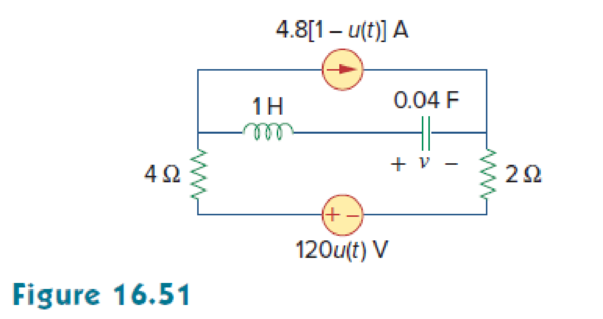
For the circuit in Fig. 16.51, find v(t) for t > 0.
Find the expression of voltage
Answer to Problem 28P
The expression of voltage
Explanation of Solution
Given data:
Refer to Figure 16.51 in the textbook.
Formula used:
Write an expression to calculate the value of step input.
Write a general expression to calculate the impedance of a resistor in s-domain.
Here,
Write a general expression to calculate the impedance of an inductor in s-domain.
Here,
Write a general expression to calculate the impedance of a capacitor in s-domain.
Here,
Calculation:
The given circuit is redrawn as shown in Figure 1.
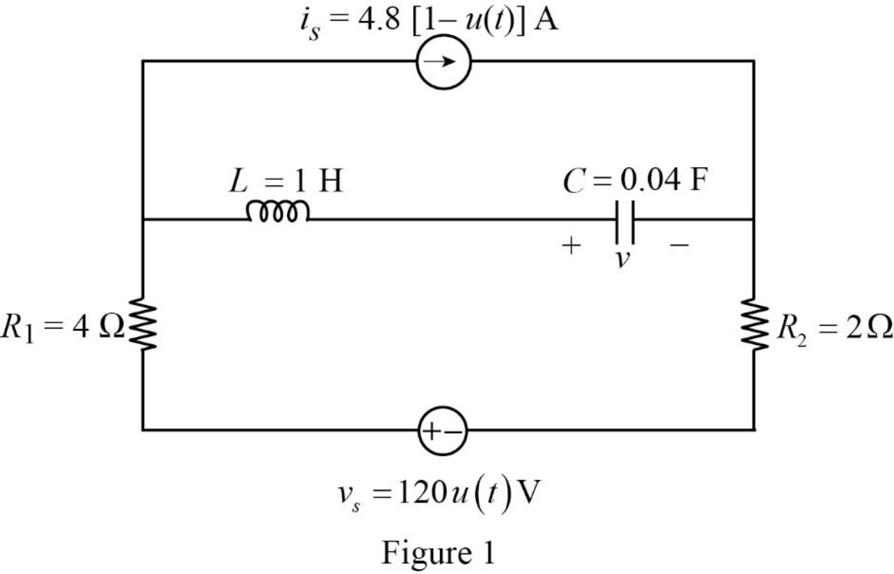
For a DC circuit, at steady state condition when time
The value of current source is calculated as follows:
The value of voltage source is calculated as follows:
Since the value of voltage source is zero it is short circuited.
Now, the Figure 1 is reduced as shown in Figure 2.
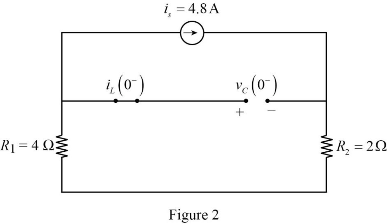
Refer to Figure 2, the capacitor is connected in parallel with the series connected resistors
Refer to Figure 2, since the capacitor is open circuited there is no current flow through the inductor.
The current through inductor and voltage across capacitor is always continuous so that,
For time
The value of current source is calculated as follows:
Since the value of current source is zero it is open circuited.
Now, the Figure 1 is reduced as shown in Figure 3.
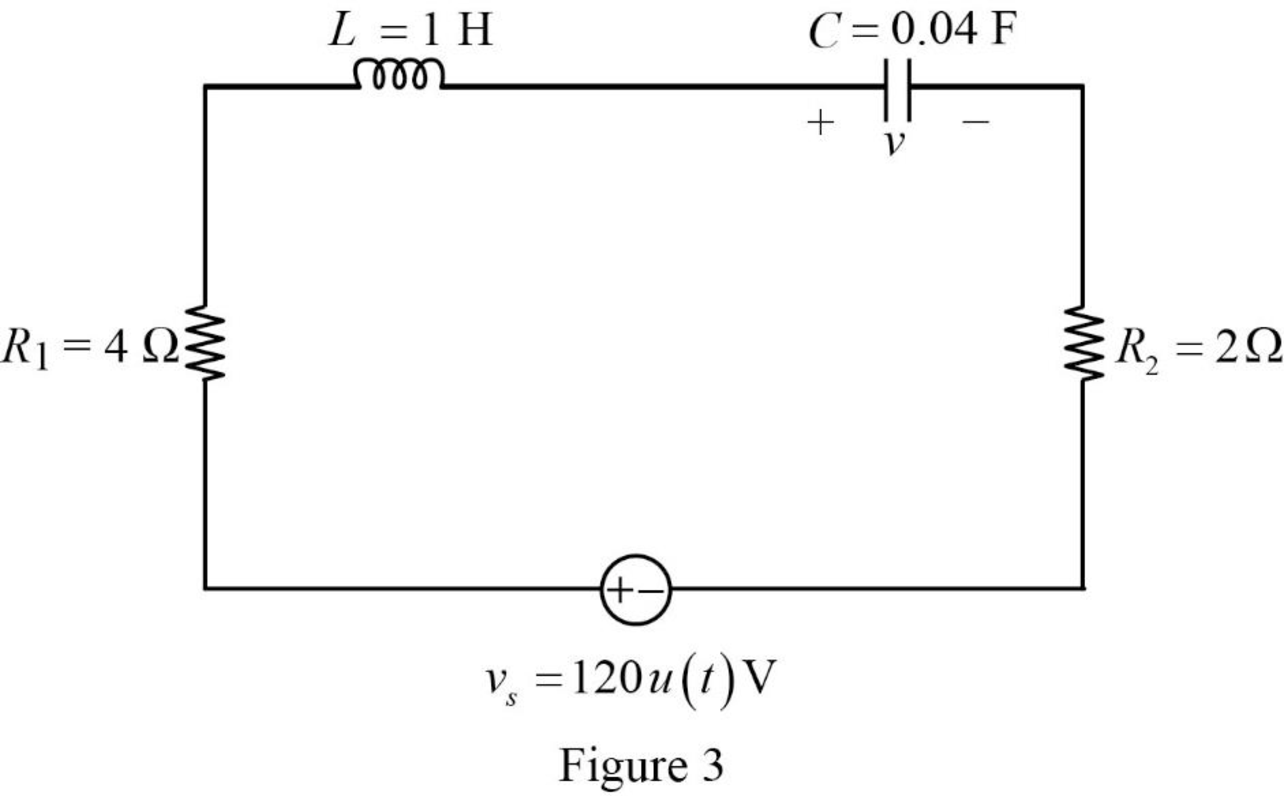
Substitute
Substitute
Substitute
Substitute
Apply Laplace transform for
Using element transformation methods with initial conditions convert the Figure 3 into s-domain.
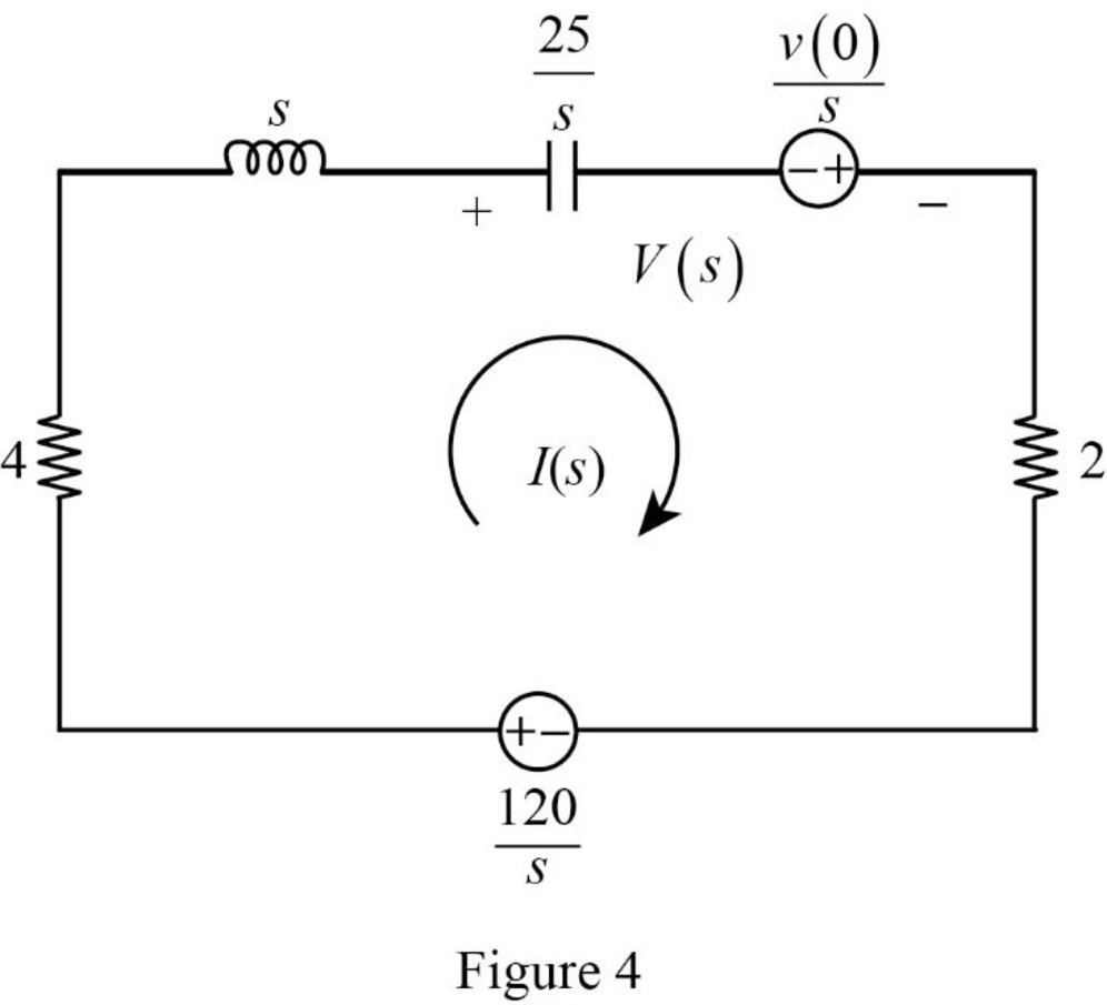
Apply Kirchhoff’s voltage law for the circuit shown in Figure 4.
Substitute
Simplify the above equation to find
From the equation (4), the characteristic equation is
Write a general expression to calculate the roots of quadratic equation
Comparing the equation (5) with the equation
Substitute
Simplify the above equation to find
Substitute the roots of characteristic equation in equation (4) to find
Refer to Figure 4, the voltage
Substitute
Assume,
Substitute equation (8) in equation (7).
Take partial fraction for equation (8).
The equation (10) can also be written as follows:
Simplify the above equation as follows:
Substitute
Simplify the above equation to find
Substitute
Simplify the above equation to find
Substitute
Simplify the above equation to find
Substitute
Substitute
Apply inverse Laplace transform for above equation to find
Simplify the above equation to find
Conclusion:
Thus, the expression of voltage
Want to see more full solutions like this?
Chapter 16 Solutions
EE 98: Fundamentals of Electrical Circuits - With Connect Access


- 23bcarrow_forwardDraw the small-signal equivalent circuit of a single transistor amplifier given in figure B1b. Assume the current source to be ideal. Determine the Open-loop transfer function, pole frequency and gain-bandwidth product all in terms of transistor parameters 9m, To and CL. If the load capacitance is 1pF and the necessary unity gain frequency is 600MHz, find the gm for this transistor. V₁ V₁ CLarrow_forward23baarrow_forward
 Introductory Circuit Analysis (13th Edition)Electrical EngineeringISBN:9780133923605Author:Robert L. BoylestadPublisher:PEARSON
 Delmar's Standard Textbook Of ElectricityElectrical EngineeringISBN:9781337900348Author:Stephen L. HermanPublisher:Cengage Learning
 Programmable Logic ControllersElectrical EngineeringISBN:9780073373843Author:Frank D. PetruzellaPublisher:McGraw-Hill Education
 Fundamentals of Electric CircuitsElectrical EngineeringISBN:9780078028229Author:Charles K Alexander, Matthew SadikuPublisher:McGraw-Hill Education
 Electric Circuits. (11th Edition)Electrical EngineeringISBN:9780134746968Author:James W. Nilsson, Susan RiedelPublisher:PEARSON
 Engineering ElectromagneticsElectrical EngineeringISBN:9780078028151Author:Hayt, William H. (william Hart), Jr, BUCK, John A.Publisher:Mcgraw-hill Education,