
EE 98: Fundamentals of Electrical Circuits - With Connect Access
6th Edition
ISBN: 9781259981807
Author: Alexander
Publisher: MCG
expand_more
expand_more
format_list_bulleted
Videos
Textbook Question
Chapter 16, Problem 49P
Find i0(t) for t > 0 in the circuit in Fig. 16.72.
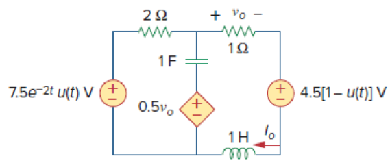
Figure 16.72
Expert Solution & Answer
Want to see the full answer?
Check out a sample textbook solution
Students have asked these similar questions
If C is the circle |z|=4 evaluate ff(z)dz for each of the following
functions using residue.
Z
(a)f(z) = z²-1
Z+1
1
(b)f(z) =
=
(c)f(z)
=
z²(z+2)
z(z-2)³
z²
1
1
(d) f(z) =
=
(e) f(z) =
(f) f(z) =
(z²+3z+2)²
z²+z+1
z(z²+6z+4)
5. Answer the following questions. Take help from ChatGPT to answer these questions (if
you need). Write the answers briefly using your own words with no more than two sentences,
and check whether ChatGPT is giving you the appropriate answers in the context of our
class.
a) What is the Bode plot? What kind of input do we consider for the frequency-response-
based method?
b) What is the advantage of design using the frequency-response method?
c) Define gain margin, phase margin, gain crossover frequency, and phase crossover
frequency.
Phase (deg)
3. The Bode diagram of a system is shown below.
Magnitude (dB)
System: sys
-10
Frequency (rad/s): 0.141
Magnitude (dB): -15.6
-20
-30
40
-50
-60
0
-45
-90
-135
101
10°
Bode Diagram
System: sys
Frequency (radis): 10
Magnitude (dB): -18.9
System: sys
Frequency (rad/s): 10
Phase (deg):-52.2
101
Frequency (rad/s)
102
103
Find the steady-state output of the system for each of the following inputs.
a) u(t) = 100
b) u(t) 100 cos(10 t + 10°)
=
c) u(t) = 500 + 200 cos(10 t + 10°)
Chapter 16 Solutions
EE 98: Fundamentals of Electrical Circuits - With Connect Access
Ch. 16.2 - Determine vo(t) in the circuit of Fig. 16.6,...Ch. 16.2 - Prob. 2PPCh. 16.2 - Prob. 3PPCh. 16.3 - For the circuit shown in Fig. 16.12 with the same...Ch. 16.3 - Prob. 5PPCh. 16.3 - The initial energy in the circuit of Fig. 16.17 is...Ch. 16.4 - Prob. 7PPCh. 16.4 - Prob. 8PPCh. 16.4 - Prob. 9PPCh. 16.5 - Obtain the state variable model for the circuit...
Ch. 16.5 - Prob. 11PPCh. 16.5 - Prob. 12PPCh. 16.6 - For what value of is the circuit in Fig. 16.29...Ch. 16.6 - Prob. 14PPCh. 16.6 - Prob. 15PPCh. 16.6 - Synthesize the function Vo(s)Vin=2ss2+6s+10 using...Ch. 16 - Prob. 1RQCh. 16 - The current through an RL series circuit with...Ch. 16 - Prob. 3RQCh. 16 - Prob. 4RQCh. 16 - Prob. 5RQCh. 16 - Prob. 6RQCh. 16 - Prob. 7RQCh. 16 - Prob. 8RQCh. 16 - Prob. 9RQCh. 16 - Prob. 10RQCh. 16 - The current in an RLC circuit is described by...Ch. 16 - The differential equation that describes the...Ch. 16 - Prob. 3PCh. 16 - If R = 20 , L = 0.6 H, what value of C will make...Ch. 16 - The responses of a series RLC circuit are vc(t) =...Ch. 16 - Prob. 6PCh. 16 - Prob. 7PCh. 16 - Prob. 8PCh. 16 - Prob. 9PCh. 16 - The step responses of a series RLC circuit are Vc...Ch. 16 - The step response of a parallel RLC circuit is v =...Ch. 16 - Prob. 12PCh. 16 - Prob. 13PCh. 16 - Prob. 14PCh. 16 - For the circuit in Fig. 16.38. calculate the value...Ch. 16 - The capacitor in the circuit of Fig. 16.39 is...Ch. 16 - If is(t) = 7.5e2t u(t) A in the circuit shown in...Ch. 16 - Find v(t), t 0 in the circuit of Fig. 16.41. Let...Ch. 16 - The switch in Fig. 16.42 moves from position A to...Ch. 16 - Find i(t) for t 0 in the circuit of Fig. 16.43.Ch. 16 - In the circuit of Fig. 16.44, the switch moves...Ch. 16 - Find the voltage across the capacitor as a...Ch. 16 - Obtain v (t) for t 0 in the circuit of Fig....Ch. 16 - The switch in the circuit of Fig. 16.47 has been...Ch. 16 - Calculate v(t) for t 0 in the circuit of Fig....Ch. 16 - Prob. 26PCh. 16 - Find v (t) for t 0 in the circuit in Fig. 16.50.Ch. 16 - For the circuit in Fig. 16.51, find v(t) for t 0.Ch. 16 - Prob. 29PCh. 16 - Find vo(t), for all t 0, in the circuit of Fig....Ch. 16 - Prob. 31PCh. 16 - For the network in Fig. 16.55, solve for i(t) for...Ch. 16 - Using Fig. 16.56, design a problem to help other...Ch. 16 - Prob. 34PCh. 16 - Prob. 35PCh. 16 - Prob. 36PCh. 16 - Prob. 37PCh. 16 - The switch in the circuit of Fig. 16.61 is moved...Ch. 16 - Prob. 39PCh. 16 - Prob. 40PCh. 16 - Prob. 41PCh. 16 - Prob. 42PCh. 16 - Prob. 43PCh. 16 - Prob. 44PCh. 16 - Find v(t) for t 0 in the circuit in Fig. 16.68.Ch. 16 - Prob. 46PCh. 16 - Determine io(t) in the network shown in Fig....Ch. 16 - Prob. 48PCh. 16 - Find i0(t) for t 0 in the circuit in Fig. 16.72....Ch. 16 - Prob. 50PCh. 16 - In the circuit of Fig. 16.74, find i(t) for t 0.Ch. 16 - Prob. 52PCh. 16 - In the circuit of Fig. 16.76, the switch has been...Ch. 16 - Prob. 54PCh. 16 - Prob. 55PCh. 16 - Calculate io(t) for t 0 in the network of Fig....Ch. 16 - Prob. 57PCh. 16 - Prob. 58PCh. 16 - Find vo(t) in the circuit of Fig. 16.82 if vx(0) =...Ch. 16 - Prob. 60PCh. 16 - Prob. 61PCh. 16 - Using Fig. 16.85, design a problem to help other...Ch. 16 - Consider the parallel RLC circuit of Fig. 16.86....Ch. 16 - The switch in Fig. 16.87 moves from position 1 to...Ch. 16 - For the RLC circuit shown in Fig. 16.88, find the...Ch. 16 - For the op amp circuit in Fig. 16.89, find v0(t)...Ch. 16 - Given the op amp circuit in Fig. 16.90, if v1(0+)...Ch. 16 - Prob. 68PCh. 16 - Prob. 69PCh. 16 - Using Fig. 16.93, design a problem to help other...Ch. 16 - Prob. 71PCh. 16 - The transfer function of a system is H(s)=s23s+1...Ch. 16 - Prob. 73PCh. 16 - Design a problem to help other students better...Ch. 16 - Prob. 75PCh. 16 - For the circuit in Fig. 16.95, find H(s) =...Ch. 16 - Obtain the transfer function H(s) = VoVs for the...Ch. 16 - Prob. 78PCh. 16 - For the circuit in Fig. 16.97, find: (a) I1/Vs (b)...Ch. 16 - Refer to the network in Fig. 16.98. Find the...Ch. 16 - Prob. 81PCh. 16 - Prob. 82PCh. 16 - Refer to the RL circuit in Fig. 16.101. Find: (a)...Ch. 16 - A parallel RL circuit has R = 4 and L = 1 H. The...Ch. 16 - Prob. 85PCh. 16 - Prob. 86PCh. 16 - Prob. 87PCh. 16 - Prob. 88PCh. 16 - Develop the state equations for the circuit shown...Ch. 16 - Prob. 90PCh. 16 - Prob. 91PCh. 16 - Prob. 92PCh. 16 - Prob. 93PCh. 16 - Prob. 94PCh. 16 - Prob. 95PCh. 16 - Prob. 96PCh. 16 - A system is formed by cascading two systems as...Ch. 16 - Determine whether the op amp circuit in Fig....Ch. 16 - It is desired realize the transfer function...Ch. 16 - Prob. 100PCh. 16 - Prob. 101PCh. 16 - Synthesize the transfer function...Ch. 16 - Prob. 103CPCh. 16 - Prob. 104CPCh. 16 - Prob. 105CP
Knowledge Booster


Learn more about
Need a deep-dive on the concept behind this application? Look no further. Learn more about this topic, electrical-engineering and related others by exploring similar questions and additional content below.Similar questions
- Phase (deg) 270 4. Consider a closed-loop system with unity (negative) feedback. The Bode diagram of the open-loop transfer function is given below. Magnitude (dB) -500 -150 -50 10 dB System Frequency (eds): 6.63 Magnitude (B) 0.0778 Буку Frequency(): 10.1 Magnitude ()-705 Frequency(6.63 Phase (deg): -144 Frequency (rad): 10.1 Phase (deg): -180 101 Frequency (rad) a) Find the gain margin, phase margin, gain crossover frequency, and phase crossover frequency. b) Is the closed-loop system stable? What is the steady-state error for step-input?arrow_forwardelectric plantsarrow_forwardsolve and show workarrow_forward
- z+4 What is the value of cz²+2z+5 dz a) If C is the circle |z|=1. c) If C is the circle |z+1+i|=2. b) If C is the circle |z+1-i|=2.arrow_forwardApplication of Complex Inversion Integral for Inverse Z-transform Find Z-1 (z-1)(z-2) }arrow_forwardz+4 What is the value of cz²+2z+5 a) If C is the circle |z|=1. dz b) If C is the circle |z+1-i|=2. c) If C is the circle |z+1+i|=2.arrow_forward
- z+4 What is the value of √cz²+2z+5 dz Sc a) If C is the circle |z|=1. c) If C is the circle |z+1+i|=2. b) If C is the circle |z+1-i|=2.arrow_forwardz+1 What is the value of Sc 73. C -2z² 3-zzz dz i) ii) iii) If C is the circle |z|=1. If C is the circle |z-2-i|=2. If C is the circle |z-1-2i|=2.arrow_forwardApplication of Complex Inversion Integral for Inverse Z-transform Find Z-1 {(2-1)(2+2)}arrow_forward
- 4z Find the residue of f(z) = (z-3)(z+1)²arrow_forwardwhat is the integral of f(z): -3z+4 = around the circle z(z-1)(z-2) |z|=3/2?arrow_forward1. The communication channel bandwidth uses is 25 MHz centered at 1GHz and uses BPSK. The noise power spectral density of the channel is 10^-9 W/Hz. The channel loss between the transmitter and receiver is 25dB. The application requires a BER of less than 10^-4. Determine the minimum transmit power required.arrow_forward
arrow_back_ios
SEE MORE QUESTIONS
arrow_forward_ios
Recommended textbooks for you
 Introductory Circuit Analysis (13th Edition)Electrical EngineeringISBN:9780133923605Author:Robert L. BoylestadPublisher:PEARSON
 Delmar's Standard Textbook Of ElectricityElectrical EngineeringISBN:9781337900348Author:Stephen L. HermanPublisher:Cengage Learning
 Programmable Logic ControllersElectrical EngineeringISBN:9780073373843Author:Frank D. PetruzellaPublisher:McGraw-Hill Education
 Fundamentals of Electric CircuitsElectrical EngineeringISBN:9780078028229Author:Charles K Alexander, Matthew SadikuPublisher:McGraw-Hill Education
 Electric Circuits. (11th Edition)Electrical EngineeringISBN:9780134746968Author:James W. Nilsson, Susan RiedelPublisher:PEARSON
 Engineering ElectromagneticsElectrical EngineeringISBN:9780078028151Author:Hayt, William H. (william Hart), Jr, BUCK, John A.Publisher:Mcgraw-hill Education,
Introductory Circuit Analysis (13th Edition)
Electrical Engineering
ISBN:9780133923605
Author:Robert L. Boylestad
Publisher:PEARSON
Delmar's Standard Textbook Of Electricity
Electrical Engineering
ISBN:9781337900348
Author:Stephen L. Herman
Publisher:Cengage Learning
Programmable Logic Controllers
Electrical Engineering
ISBN:9780073373843
Author:Frank D. Petruzella
Publisher:McGraw-Hill Education
Fundamentals of Electric Circuits
Electrical Engineering
ISBN:9780078028229
Author:Charles K Alexander, Matthew Sadiku
Publisher:McGraw-Hill Education
Electric Circuits. (11th Edition)
Electrical Engineering
ISBN:9780134746968
Author:James W. Nilsson, Susan Riedel
Publisher:PEARSON
Engineering Electromagnetics
Electrical Engineering
ISBN:9780078028151
Author:Hayt, William H. (william Hart), Jr, BUCK, John A.
Publisher:Mcgraw-hill Education,
Systems and Simulation - Lecture 3: Modelling of Mechanical systems; Author: bioMechatronics Lab;https://www.youtube.com/watch?v=fMcDdyoC9mA;License: Standard Youtube License