
ENGINEERING CIRCUIT...(LL)>CUSTOM PKG.<
9th Edition
ISBN: 9781260540666
Author: Hayt
Publisher: MCG CUSTOM
expand_more
expand_more
format_list_bulleted
Videos
Textbook Question
Chapter 14, Problem 56E
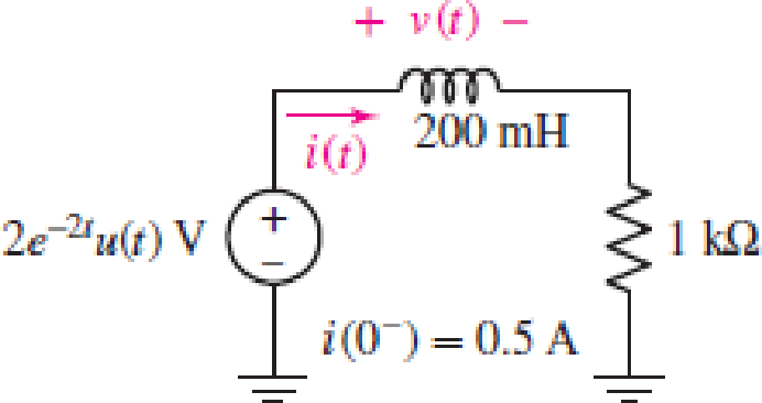
For the circuit of Fig. 14.54, (a) draw both s-domain equivalent circuits; (b) choose one and solve for V(s); (c) determine v(t).
Expert Solution & Answer
Want to see the full answer?
Check out a sample textbook solution
Students have asked these similar questions
I hope the solution is on paper and not
artificial intelligence.
The subject is control system
I hope the solution is on paper and not artificial intelligence.
Vs
R1
R2
ww
ww
21x
R3
Define the Thevenin equivalent of the above circuit where R1= 10 52, R2= 30 S2, R3 = 30 12,
Vs = 70 V.
VThevenin
Number
V
RThevenin
= Number
Ω
Chapter 14 Solutions
ENGINEERING CIRCUIT...(LL)>CUSTOM PKG.<
Ch. 14.1 - Identify all the complex frequencies present in...Ch. 14.1 - Use real constants A, B, C, , and so forth, to...Ch. 14.2 - Let f (t) = 6e2t [u(t + 3) u(t 2)]. Find the (a)...Ch. 14.3 - Prob. 4PCh. 14.3 - Prob. 5PCh. 14.4 - Prob. 6PCh. 14.4 - Prob. 7PCh. 14.4 - Prob. 8PCh. 14.4 - Prob. 9PCh. 14.5 - Prob. 10P
Ch. 14.5 - Prob. 11PCh. 14.5 - Prob. 12PCh. 14.6 - Prob. 13PCh. 14.7 - Prob. 14PCh. 14.7 - Prob. 15PCh. 14.8 - Find the mesh currents i1 and i2 in the circuit of...Ch. 14.8 - Prob. 17PCh. 14.8 - Prob. 18PCh. 14.9 - Using the method of source transformation, reduce...Ch. 14.9 - Prob. 20PCh. 14.10 - The parallel combination of 0.25 mH and 5 is in...Ch. 14.11 - Prob. 22PCh. 14.11 - Prob. 23PCh. 14.11 - Prob. 24PCh. 14.11 - Prob. 25PCh. 14.12 - Prob. 26PCh. 14 - Determine the conjugate of each of the following:...Ch. 14 - Compute the complex conjugate of each of the...Ch. 14 - Several real voltages are written down on a piece...Ch. 14 - State the complex frequency or frequencies...Ch. 14 - For each of the following functions, determine the...Ch. 14 - Use real constants A, B, , , etc. to construct the...Ch. 14 - The following voltage sources AeBt cos(Ct + ) are...Ch. 14 - Prob. 8ECh. 14 - Compute the real part of each of the following...Ch. 14 - Your new assistant has measured the signal coming...Ch. 14 - Prob. 11ECh. 14 - Prob. 12ECh. 14 - Prob. 13ECh. 14 - Prob. 14ECh. 14 - Prob. 15ECh. 14 - Prob. 16ECh. 14 - Determine F(s) if f (t) is equal to (a) 3u(t 2);...Ch. 14 - Prob. 18ECh. 14 - Prob. 19ECh. 14 - Prob. 20ECh. 14 - Prob. 21ECh. 14 - Evaluate the following: (a)[(2t)]2 at t = 1;...Ch. 14 - Evaluate the following expressions at t = 0: (a)...Ch. 14 - Prob. 24ECh. 14 - Prob. 25ECh. 14 - Prob. 26ECh. 14 - Prob. 27ECh. 14 - Prob. 28ECh. 14 - Prob. 29ECh. 14 - Prob. 30ECh. 14 - Prob. 31ECh. 14 - Prob. 32ECh. 14 - Prob. 33ECh. 14 - Obtain the time-domain expression which...Ch. 14 - Prob. 35ECh. 14 - Prob. 36ECh. 14 - Prob. 37ECh. 14 - Prob. 38ECh. 14 - Prob. 39ECh. 14 - Prob. 40ECh. 14 - Prob. 41ECh. 14 - Obtain, through purely legitimate means, an...Ch. 14 - Prob. 43ECh. 14 - Employ the initial-value theorem to determine the...Ch. 14 - Prob. 45ECh. 14 - Prob. 46ECh. 14 - Prob. 47ECh. 14 - Prob. 48ECh. 14 - Prob. 49ECh. 14 - Prob. 52ECh. 14 - Determine v(t) for t 0 for the circuit shown in...Ch. 14 - Prob. 54ECh. 14 - Prob. 55ECh. 14 - For the circuit of Fig. 14.54, (a) draw both...Ch. 14 - Prob. 58ECh. 14 - Prob. 59ECh. 14 - Prob. 60ECh. 14 - For the circuit shown in Fig. 14.58, let is1 =...Ch. 14 - Prob. 63ECh. 14 - Prob. 64ECh. 14 - For the circuit shown in Fig. 14.62, determine the...Ch. 14 - Prob. 67ECh. 14 - Prob. 68ECh. 14 - Determine the poles and zeros of the following...Ch. 14 - Use appropriate means to ascertain the poles and...Ch. 14 - Prob. 71ECh. 14 - For the network represented schematically in Fig....Ch. 14 - Prob. 73ECh. 14 - Prob. 74ECh. 14 - Prob. 75ECh. 14 - Prob. 76ECh. 14 - Prob. 77ECh. 14 - Prob. 78ECh. 14 - Prob. 79ECh. 14 - Prob. 80ECh. 14 - Prob. 81ECh. 14 - Prob. 82ECh. 14 - Design a circuit which produces the transfer...Ch. 14 - Prob. 84ECh. 14 - Prob. 85ECh. 14 - An easy way to get somebodys attention is to use a...Ch. 14 - Prob. 87E
Knowledge Booster


Learn more about
Need a deep-dive on the concept behind this application? Look no further. Learn more about this topic, electrical-engineering and related others by exploring similar questions and additional content below.Similar questions
- R1 ww + R3 15+ www R2 R4 ww With the circuit diagram shown above and the values of the circuit elements listed below, find i1, 12, v1, and v2. Is = 10A, R1 = 7 ohms, R2 = 9 ohms, R3 = 7 ohms, R4 = 8 ohms (a) i1 = Number A (b) 12 = Number A (c) v1 = Number V (d) v2 = Number Varrow_forward15 ww 22 R2 ли i4 1+ V4 R1 ww R3 Solve for current i4 using superposition where R1 = 902, R2 = 36052, R3 = 360 V, and 15 = 5 A. 27052, V4 = i4 due to voltage source (V4) alone: Number A i4 due to current source (15) alone: Number A i4 = Numberarrow_forwardPV Array Va DC/DC Converter Control Circuit ис V R Fig. 2. Principle of using DC/DC converter to implement electronic load [2] 4.5 1.5 -0.5 SEPIC Converters in SOM 0 0.2 0.4 0.6 0.8 Time SEPIC Converters in SOM M 0 0.2 0.4 0.6 0.8 Time Current I-V Curve (a) 8888888 P-V Curve 0 20 40 60 80 Voltage 0 20 40 60 Voltage 80 (b) Fig. 3. Experimental results of I-V and P-V curves [2]arrow_forward
- R1 ww + R3 15+ www R2 R4 ww With the circuit diagram shown above and the values of the circuit elements listed below, find i1, 12, v1, and v2. Is = 10A, R1 = 7 ohms, R2 = 9 ohms, R3 = 7 ohms, R4 = 8 ohms (a) i1 = Number A (b) 12 = Number A (c) v1 = Number V (d) v2 = Number Varrow_forwardFind the equivalent resistance between terminals a and b in the circuit below where R₁ =6 N, R₂=12, R3=22, R4=22, and R5=150. 22 R2 R1 R5 oa R3 R4 ob Req= Number Ωarrow_forwardA Thévenin equivalent can also be determined from measurements made at the pair of terminals of interest. Assume the following measurements were made at the terminals a,b in the figure below. When a 25 k2 resistor is connected to the terminals a,b, the voltage is measured and found to be 105 V. When a 2 k resistor is connected to the terminals a,b, the voltage is measured and found to be 13 V. Find the Thévenin equivalent of the network with respect to the terminals a,b. Linear resistive network with independent and dependent sources RTh = Number ΚΩ VTh= Number V a barrow_forward
- I need help with this problem and an explanation of the solution for the image described below. (Introduction to Signals and Systems)arrow_forwardI need help with this problem and an explanation of the solution for the image described below. (Introduction to Signals and Systems)arrow_forwardI need help with this problem and an explanation of the solution for the image described below. (Introduction to Signals and Systems)arrow_forward
arrow_back_ios
SEE MORE QUESTIONS
arrow_forward_ios
Recommended textbooks for you
 Introductory Circuit Analysis (13th Edition)Electrical EngineeringISBN:9780133923605Author:Robert L. BoylestadPublisher:PEARSON
 Delmar's Standard Textbook Of ElectricityElectrical EngineeringISBN:9781337900348Author:Stephen L. HermanPublisher:Cengage Learning
 Programmable Logic ControllersElectrical EngineeringISBN:9780073373843Author:Frank D. PetruzellaPublisher:McGraw-Hill Education
 Fundamentals of Electric CircuitsElectrical EngineeringISBN:9780078028229Author:Charles K Alexander, Matthew SadikuPublisher:McGraw-Hill Education
 Electric Circuits. (11th Edition)Electrical EngineeringISBN:9780134746968Author:James W. Nilsson, Susan RiedelPublisher:PEARSON
 Engineering ElectromagneticsElectrical EngineeringISBN:9780078028151Author:Hayt, William H. (william Hart), Jr, BUCK, John A.Publisher:Mcgraw-hill Education,
Introductory Circuit Analysis (13th Edition)
Electrical Engineering
ISBN:9780133923605
Author:Robert L. Boylestad
Publisher:PEARSON
Delmar's Standard Textbook Of Electricity
Electrical Engineering
ISBN:9781337900348
Author:Stephen L. Herman
Publisher:Cengage Learning
Programmable Logic Controllers
Electrical Engineering
ISBN:9780073373843
Author:Frank D. Petruzella
Publisher:McGraw-Hill Education
Fundamentals of Electric Circuits
Electrical Engineering
ISBN:9780078028229
Author:Charles K Alexander, Matthew Sadiku
Publisher:McGraw-Hill Education
Electric Circuits. (11th Edition)
Electrical Engineering
ISBN:9780134746968
Author:James W. Nilsson, Susan Riedel
Publisher:PEARSON
Engineering Electromagnetics
Electrical Engineering
ISBN:9780078028151
Author:Hayt, William H. (william Hart), Jr, BUCK, John A.
Publisher:Mcgraw-hill Education,
02 - Sinusoidal AC Voltage Sources in Circuits, Part 1; Author: Math and Science;https://www.youtube.com/watch?v=8zMiIHVMfaw;License: Standard Youtube License