
Videos
(a)
Design a circuit which produces a transfer function of
(a)
Explanation of Solution
Problem design:
Synthesize a circuit that will yield the transfer function
Calculation:
The transfer function of the circuit is,
The above equation is written as,
For the above transfer function, it has two repeated zeros at
The Figure 14.39 (b) in the textbook, that shows a cascade two stages of the circuit with a zero at
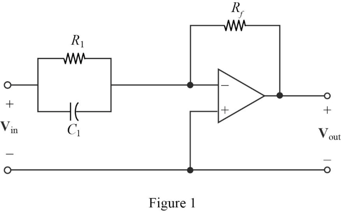
For a single zero,
Substitute
Let arbitrarily consider
Substitute
Transfer function:
The input impedance of the cascaded circuit is,
Then, write the Formula for the transfer function for the cascaded two stage amplifier.
Substitute
Thus, consider that the transfer function for
Substitute 1 for
Completing the design by letting
Since, two repeated zeros at
Therefore,
Substitute
Thus, the final design of the circuit is,
Conclusion:
Thus, a circuit is designed which produces a transfer function of
(b)
Design a circuit which produces a transfer function of
(b)
Explanation of Solution
Problem design:
Synthesize a circuit that will yield the transfer function
Calculation:
The transfer function of the circuit is,
Consider the transfer function for the cascaded circuit as below.
The above transfer function, it has two poles at
The Figure 14.39 (a) in the textbook, that shows a cascade two stages of the circuit with pole at
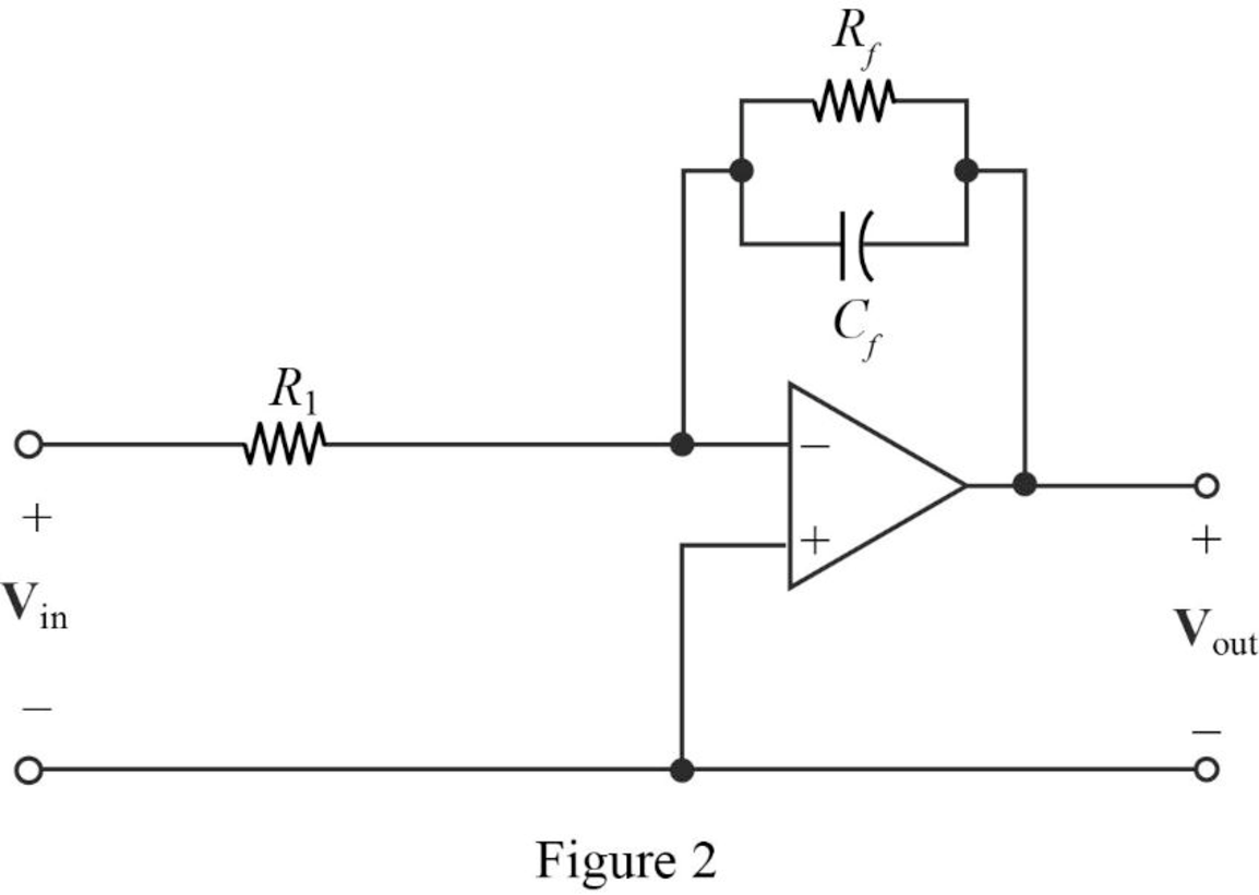
The above Figure 2, is the representation for the first stage and second stage of a cascaded circuit to be drawn.
Consider the denominator of given transfer function and the first pole as
Where,
Substitute
Let arbitrarily consider
Substitute
Transfer function:
Find the feedback impedance of the cascaded circuit in Figure 2.
Write the formula for the transfer function of the cascaded circuit in Figure 2 as follows
Substitute
Therefore, consider the transfer function for the first pole
Substitute 500 for
Completing the design by letting
Consider the denominator of given transfer function and the first pole as
Where,
Substitute
Arbitrarily consider
Substitute
Therefore, consider the transfer function for the second pole
Substitute 100 for
Completing the design by letting
Then, from the transfer function of the two stages write the complete transfer function as follows.
Substitute
Thus, the final design of the circuit is,
Conclusion:
Thus, a circuit is designed which produces a transfer function of
Want to see more full solutions like this?
Chapter 14 Solutions
ENGINEERING CIRCUIT...(LL)>CUSTOM PKG.<


- 6. Determine the type of the filter in the following figure and calculate the cut off frequency fc, show all steps.arrow_forward5. Find the Transfer Function of the following circuit. Prove that it’s a low pass filter, show all steps.arrow_forward2. Find the transfer function, show all steps.arrow_forward
- I have this fsk function code: function [x]=fsk_encode(b,s,f0,f1,N,Fs,K) % b= bit sequence vector % s(1)= output level for 0 % s(2)= output level for 1 % N= length of bit sequence % Fs= Sampling frequency y=zeros(1,N*K); %Setup output vector %for each bit calculatee the rando samples for n=1:N for k=1:K t = (k - 1) / Fs; if(b(n)==0) y((n-1)*K+k)=cos(2*pi*f0*t); % pulse=0 else y((n-1)*K+k)=cos(2*pi*f1*t); % pulse=1 end end x=y; %set output end And this is another code that calls the function in order to get the power density spectrum: clc;clear; % EE 382 Communication Systems- Lab 8 % Plots the power spectrum of the ASK modulation % First specify some parameters N=256; % number of bits per realization M=100; % number of realizations in the ensemble T=0.001; % bit duration in seconds delf =2e+3; fc=10e+3; f0=fc-delf; f1=fc+delf; Fs=8*f1; % sampling frequency (this is needed to calibrate the frequency axis) K=(T/(1/Fs)); % Define arrays for bit sequences and sampled waveforms…arrow_forwardCalculate the parameters in the figurearrow_forwardWrite the angle expression form of first null beam width FNBW) for 2/2 dipole. for 즐, 꽃 3arrow_forward
- The circuit is in the DC steady state, So all transients are passed. What are the values of 1 and V, under those conditions. P 24v + + √2 АЛАД 42 4F 3.H ww 22 eee + 203 Varrow_forwardFind the value of Vc (t) for all I That is, the complete response including natural and forced responses.) АДДА 422 OV ДААД t = 0 3F + V(t) -arrow_forward1.0 Half-power point (left) 0.5 Minor lobes Main lobe maximum direction Main lobe Half-power point (right) Half-power beamwidth (HP) Beamwidth between first nulls (BWFN) *Which of the following Lobes of an antenna Pattern 180 out of Phase the main Lobe ? And where are the ch other gems ?arrow_forward
- The normalized radiation intensity of an antenna is represented by U(0) = cos² (0) cos² (30), w/sr Find the a. half-power beamwidth HPBW (in radians and degrees) b. first-null beamwidth FNBW (in radians and degrees)arrow_forwardQ1/ Route the following flood hydrograph through a river reach for which storage duration constant = 10 hr and weighted factor = 0.25. At the start of the inflow flood, the outflow discharge is 60m³/s. Inflow (m/s) Time (hr) 140 60 100 0 4 8 12 16 120 80 40 20 Q2/ Answer the following: 1. Define water requirements and list the losses of irrigation. Q3/ Irrigation project with the following data: = 150 mm/m Root Zone Depth (RZD) = 1.1 m 15% of the net depth - Available Water PAD = 50%, Leaching Requirement Rainfall = 12 mm, = water Losses = 10% of the net depth. If the net water depth added after depletion of already available water, Calculate: gross irrigation water, and application efficiency. C= Carrow_forwardA3 m long cantilever ABC is built-in at A, partially supported at B, 2 m from A, with a force of 10 kN and carries a vertical load of 20 kN at C. A uniformly distributed bad of 5 kN/m is also applied between A and B. Determine (a) the values of the vertical reaction and built-in moment at A and (b) the deflection of the free end C of the cantilever, Develop an expression for the slope of the beam at any position and hence plot a slope diagram. E = 208GN / (m ^ 2) and 1 = 24 * 10 ^ - 6 * m ^ 4arrow_forward
 Introductory Circuit Analysis (13th Edition)Electrical EngineeringISBN:9780133923605Author:Robert L. BoylestadPublisher:PEARSON
 Delmar's Standard Textbook Of ElectricityElectrical EngineeringISBN:9781337900348Author:Stephen L. HermanPublisher:Cengage Learning
 Programmable Logic ControllersElectrical EngineeringISBN:9780073373843Author:Frank D. PetruzellaPublisher:McGraw-Hill Education
 Fundamentals of Electric CircuitsElectrical EngineeringISBN:9780078028229Author:Charles K Alexander, Matthew SadikuPublisher:McGraw-Hill Education
 Electric Circuits. (11th Edition)Electrical EngineeringISBN:9780134746968Author:James W. Nilsson, Susan RiedelPublisher:PEARSON
 Engineering ElectromagneticsElectrical EngineeringISBN:9780078028151Author:Hayt, William H. (william Hart), Jr, BUCK, John A.Publisher:Mcgraw-hill Education,