
Videos
Design a circuit which produces the transfer function
Design a circuit which produces a transfer function of
Explanation of Solution
Given data:
The given transfer function is,
Calculation:
The transfer function of the circuit is,
Equation (1) is written as,
For numerator:
From equation (2), for the numerator
The Figure 14.39 (b) in the textbook, that shows a cascade two stages of the circuit with a zero at
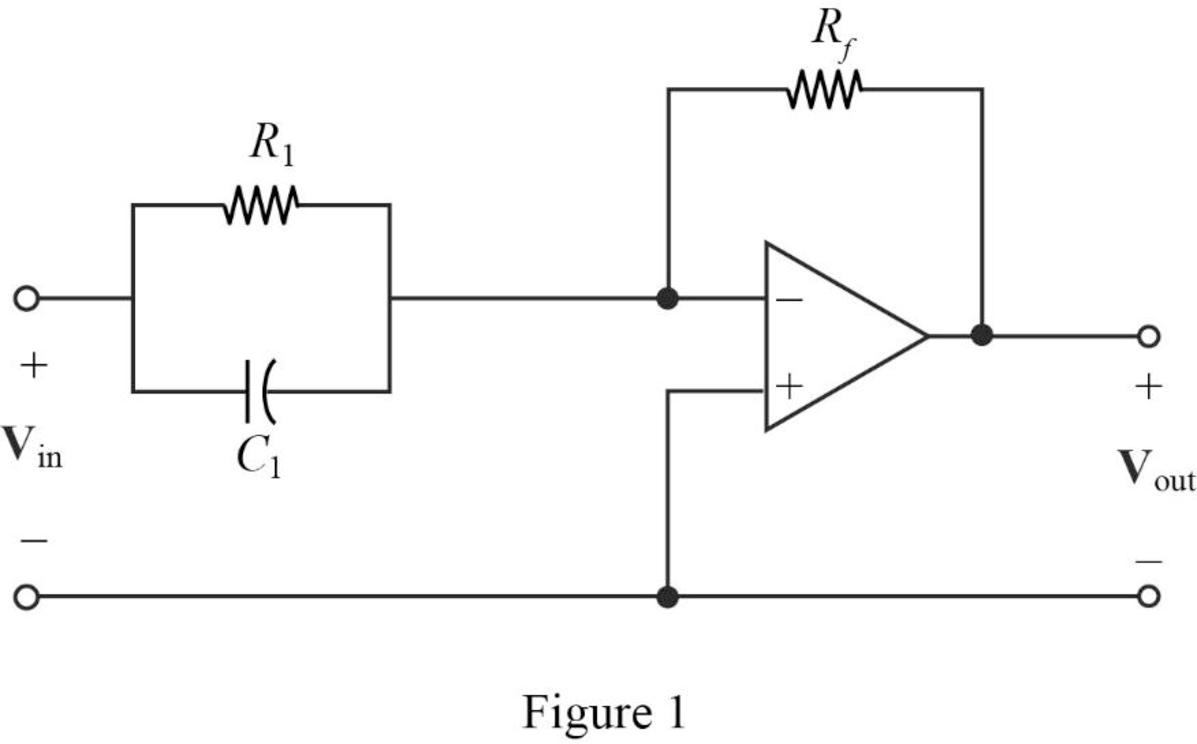
From the Figure 1, a single zero can be written as,
Substitute
Consider the value of
Substitute
Transfer function:
The input impedance of the cascaded circuit in Figure 1 is,
Then, write the Formula for the transfer function for the cascaded two stage amplifier.
Substitute
Thus, consider that the transfer function for
Substitute 50 for
Completing the design by letting
Thus, the final design of the circuit is,
For denominator:
From the transfer function shown in equation (2), it has two repeated poles at
The Figure 14.39 (a) in the textbook, that shows a cascade two stages of the circuit with pole at
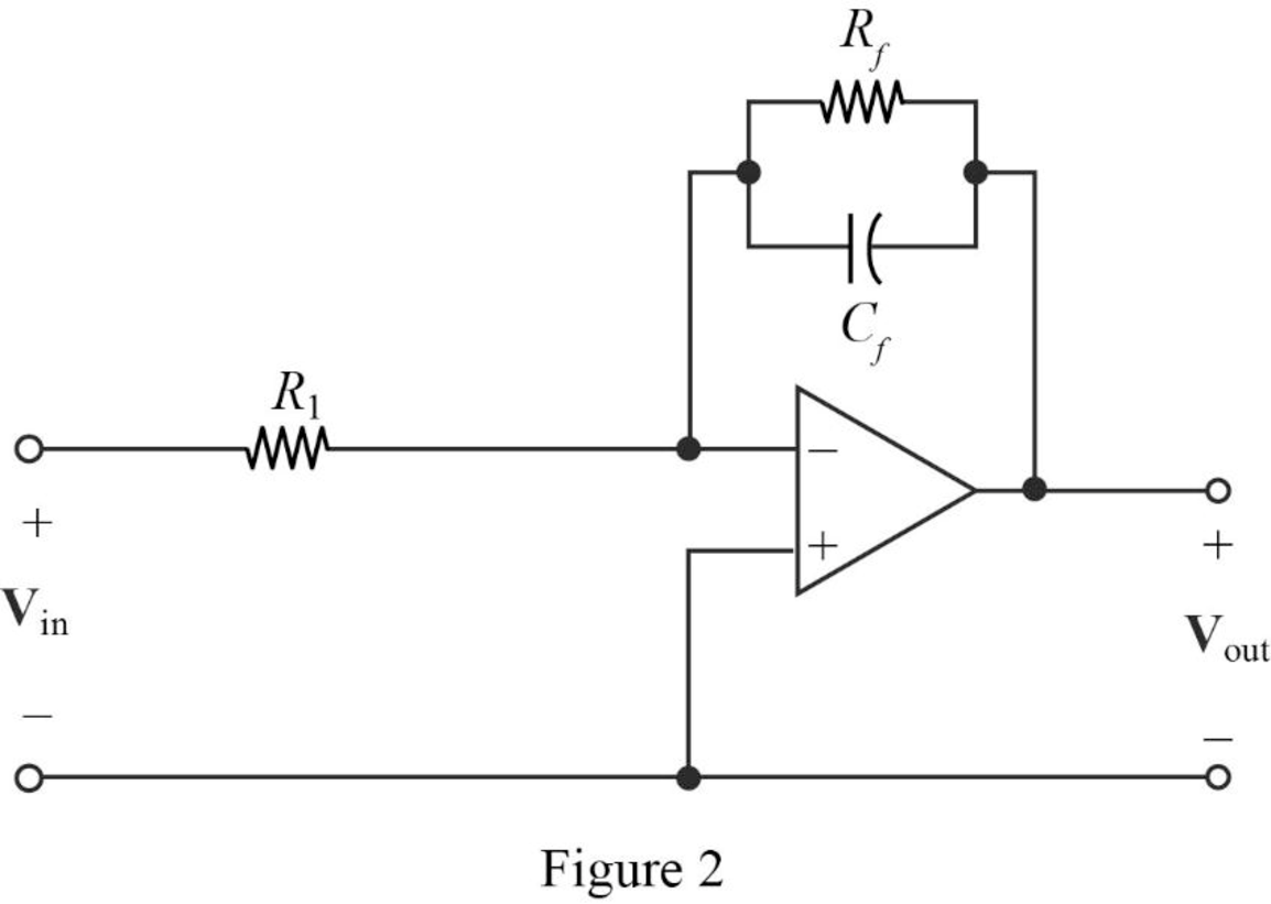
Consider that the cascaded circuit for the two poles representation as shown in Figure 2.
From Figure 2, and the denominator of given transfer function a first pole at
Where, the circuit parameters are considered as
Substitute
Let arbitrarily consider
Substitute 13.3 for
Transfer Function:
Find the feedback impedance of the cascaded circuit in Figure 2.
Write the formula for the transfer function of the cascaded circuit in Figure 2 as follows
Substitute
Therefore, consider the transfer function
Substitute 75 for
Completing the design by letting
Since, two repeated poles are at same
Therefore, the complete transfer function for the denominator part is,
Substitute
Thus, the final design of the two stages cascaded circuit for the denominator part is,
Thus, the overall transfer function of the complete circuit using the transfer function of numerator
Substitute
The input will be inverted, and adding an inverting amplifier with gain of 1 to provide the transfer function as follows.
Conclusion:
Thus, a circuit is designed which produces a transfer function of
Want to see more full solutions like this?
Chapter 14 Solutions
ENGINEERING CIRCUIT...(LL)>CUSTOM PKG.<
Additional Engineering Textbook Solutions
Starting Out with Programming Logic and Design (5th Edition) (What's New in Computer Science)
Database Concepts (8th Edition)
Electric Circuits. (11th Edition)
Thermodynamics: An Engineering Approach
Modern Database Management
Mechanics of Materials (10th Edition)


- Find the Thévenin equivalent circuit for the portions of the networks in Figure external to the elements between points a and b. E = 20 VZ0° + R ww 2 ΚΩ Хо XL 000 6ΚΩ 3 ΚΩ b RLarrow_forwardWhat percentage of the full-load current of a thermally protected continuous-duty motor of more than one Hp can the trip current be, if the full-load current is 15 amperes? Ο 122 Ο 140 156 O 170arrow_forwardQ3arrow_forward
- In thinkercad can you make a parallel series circuit with a resistors and a voltage source explain how the voltage and current moves through the circuit, and explaining all the components, and if you were to break the circuit to find the current how would you do that? Please show visuals if possible.arrow_forwardIn thinkercad can you make a series circuit with a resistors and a voltage source explain how the voltage and current moves through the circuit, and explaining all the components, and if you were to break the circuit to find the current how would you do that? Please show visuals if possible.arrow_forwardIn thinkercad can you make a parallel circuit with a resistors and a voltage source explain how the voltage and current moves through the circuit, and explaining all the components, and if you were to break the circuit to find the current how would you do that? Please show visuals if possiblearrow_forward
- Q1arrow_forward2-2 -Draw V-curves for synchronous motor at no load, half load, and full load? 2-List the advantages of damper bars in synchronous machines? 3-Draw phasor diagram for alternator at unity power factor, and derive EMF equation from it?arrow_forwardconduit bending techniques and the most common anglesarrow_forward
- Question 1 Draw and complex CMOS logic and design the width-to-length ratios (W/L) of the transistors needed to implement the CMOS circuit for the following function (asuume Wp: W₁ = 2:1) n f=AB+CD+E+AD Question 2 Implement the following function using CMOS technology. f = x1(x2x3 + x4) Design the width-to-length ratios (W/L) of the transistors needed to implement the CMOS circuuit for the following function (asuume Wp: W₁ = 2:1) n Question 3 Consider the following three-pole feedback amplifier with a loop gain function: 6000× B T (jf) = 1+j f 2×10³ 1+ j f 3×10⁴ f 1+ j 4×10⁵ If ẞ=38.66×10³ determine the phase margin and the gain margin of this system (if it is stable).arrow_forwardhow to bend conduit in exact angles. and bending angles stepsarrow_forward¡ you need to connect a three phase alternator B (incoming generator) in parallel with alternator A which is connected to an infinite bus bar, what are the necessary conditions to make this connection appen properly? Explain how you can use a three lamps to achieve this connection?arrow_forward
 Introductory Circuit Analysis (13th Edition)Electrical EngineeringISBN:9780133923605Author:Robert L. BoylestadPublisher:PEARSON
 Delmar's Standard Textbook Of ElectricityElectrical EngineeringISBN:9781337900348Author:Stephen L. HermanPublisher:Cengage Learning
 Programmable Logic ControllersElectrical EngineeringISBN:9780073373843Author:Frank D. PetruzellaPublisher:McGraw-Hill Education
 Fundamentals of Electric CircuitsElectrical EngineeringISBN:9780078028229Author:Charles K Alexander, Matthew SadikuPublisher:McGraw-Hill Education
 Electric Circuits. (11th Edition)Electrical EngineeringISBN:9780134746968Author:James W. Nilsson, Susan RiedelPublisher:PEARSON
 Engineering ElectromagneticsElectrical EngineeringISBN:9780078028151Author:Hayt, William H. (william Hart), Jr, BUCK, John A.Publisher:Mcgraw-hill Education,