
EBK FUNDAMENTALS OF ELECTRIC CIRCUITS
6th Edition
ISBN: 8220102801448
Author: Alexander
Publisher: YUZU
expand_more
expand_more
format_list_bulleted
Concept explainers
Videos
Textbook Question
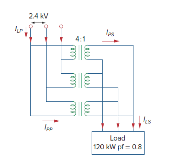
Chapter 13, Problem 74P
Consider the three-phase transformer shown in Fig. 13.136. The primary is fed by a three-phase source with line voltage of 2.4 kV rms, while the secondary supplies a three-phase 120-kW balanced load at pf of 0.8. Determine:
- (a) the type of transformer connections,
- (b) the values of ILS and IPS,
- (c) the values of ILP and IPP,
- (d) the kVA rating of each phase of the transformer.
Expert Solution & Answer
Want to see the full answer?
Check out a sample textbook solution
Students have asked these similar questions
Write a program to flash three LED's connected to ports (11, 12 & 13) respectively as shown below:
(Note: T-T3-3s & T₂= T₁=2s)
LED (pin 11)
LED2 (pin 12)
LED: (pin 13)
T' T2 T3' 14
Not use ai please
Suppose you have three push buttons connected to (B5, B6 & B7) and eight LED's connected to (Do
D7): Write a program to flash ON the odd LED's if we press the switch B7 for 0.4s, flash ON the even
LED's if we press the switch (B6 for 0.4s and flash ON all the LED's if we press the switch B5 for 0.7s.
Chapter 13 Solutions
EBK FUNDAMENTALS OF ELECTRIC CIRCUITS
Ch. 13.2 - Determine the voltage Vo in the circuit of Fig....Ch. 13.2 - Determine the phasor currents I1 and I2 in the...Ch. 13.3 - Prob. 3PPCh. 13.4 - Find the input impedance of the circuit in Fig....Ch. 13.4 - For the linear transformer in Fig. 13.26(a), find...Ch. 13.4 - Solve the problem in Example 13.1 (see Fig. 13.9)...Ch. 13.5 - The primary current to an ideal transformer rated...Ch. 13.5 - In the ideal transformer circuit of Fig. 13.38,...Ch. 13.5 - Find Vo in the circuit of Fig. 13.40. Figure 13.40...Ch. 13.6 - Refer to Fig. 13.43. If the two-winding...
Ch. 13.6 - In the autotransformer circuit of Fig. 13.45, find...Ch. 13.7 - Prob. 12PPCh. 13.8 - Prob. 13PPCh. 13.9 - Refer to Fig. 13.61. Calculate the turns ratio...Ch. 13.9 - Calculate the turns ratio of an ideal transformer...Ch. 13.9 - In Example 13.17, if the eight 100-W bulbs are...Ch. 13 - Refer to the two magnetically coupled coils of...Ch. 13 - Prob. 2RQCh. 13 - Prob. 3RQCh. 13 - Prob. 4RQCh. 13 - The ideal transformer in Fig. 13.70(a) has N2/N1 =...Ch. 13 - Prob. 6RQCh. 13 - A three-winding transformer is connected as...Ch. 13 - Prob. 8RQCh. 13 - Prob. 9RQCh. 13 - Prob. 10RQCh. 13 - For the three coupled coils in Fig. 13.72,...Ch. 13 - Using Fig. 13.73, design a problem to help other...Ch. 13 - Two coils connected in series-aiding fashion have...Ch. 13 - (a) For the coupled coils in Fig. 13.74(a), show...Ch. 13 - Two coils are mutually coupled, with L1 = 50 mH,...Ch. 13 - Given the circuit shown in Fig. 13.75, determine...Ch. 13 - For the circuit in Fig. 13.76, find Vo. Figure...Ch. 13 - Find v(t) for the circuit in Fig. 13.77.Ch. 13 - Prob. 9PCh. 13 - Find vo in the circuit of Fig. 13.79. Figure 13.79...Ch. 13 - Use mesh analysis to find ix in Fig. 13.80, where...Ch. 13 - Determine the equivalent Leq in the circuit of...Ch. 13 - For the circuit in Fig. 13.82, determine the...Ch. 13 - Obtain the Thevenin equivalent circuit for the...Ch. 13 - Find the Norton equivalent for the circuit in Fig....Ch. 13 - Obtain the Norton equivalent at terminals a-b of...Ch. 13 - In the circuit of Fig. 13.86, ZL is a 15-mH...Ch. 13 - Find the Thevenin equivalent to the left of the...Ch. 13 - Determine an equivalent T-section that can be used...Ch. 13 - Determine currents I1, I2, and I3 in the circuit...Ch. 13 - Prob. 21PCh. 13 - Find current Io in the circuit of Fig. 13.91.Ch. 13 - Let is = 5 cos (100t) A. Calculate the voltage...Ch. 13 - In the circuit of Fig. 13.93, (a) find the...Ch. 13 - Prob. 25PCh. 13 - Find Io in the circuit of Fig. 13.95. Switch the...Ch. 13 - Find the average power delivered to the 50-...Ch. 13 - In the circuit of Fig. 13.97, find the value of X...Ch. 13 - Prob. 29PCh. 13 - (a) Find the input impedance of the circuit in...Ch. 13 - Using Fig. 13.100, design a problem to help other...Ch. 13 - Two linear transformers are cascaded as shown in...Ch. 13 - Determine the input impedance of the air-core...Ch. 13 - Using Fig. 13.103, design a problem to help other...Ch. 13 - Find currents I1, I2, and I3 in the circuit of...Ch. 13 - As done in Fig. 13.33, obtain the relationships...Ch. 13 - A 2402,400-V rms step-up ideal transformer...Ch. 13 - Design a problem to help other students better...Ch. 13 - A 1,200240-V rms transformer has impedance on the...Ch. 13 - The primary of an ideal transformer with a turns...Ch. 13 - Given I2 = 2 A, determine the value of Is in Fig....Ch. 13 - For the circuit in Fig. 13.107, determine the...Ch. 13 - Obtain V1 and V2 in the ideal transformer circuit...Ch. 13 - In the ideal transformer circuit of Fig. 13.109,...Ch. 13 - For the circuit in Fig. 13.110, find the value of...Ch. 13 - (a) Find I1 and I2 in the circuit of Fig. 13.111...Ch. 13 - Prob. 47PCh. 13 - Using Fig. 13.113, design a problem to help other...Ch. 13 - Find current ix in the ideal transformer circuit...Ch. 13 - Prob. 50PCh. 13 - Use the concept of reflected impedance to find the...Ch. 13 - For the circuit in Fig. 13.117, determine the...Ch. 13 - Refer to the network in Fig. 13.118. (a) Find n...Ch. 13 - A transformer is used to match an amplifier with...Ch. 13 - For the circuit in Fig. 13.120, calculate the...Ch. 13 - Find the power absorbed by the 100- resistor in...Ch. 13 - For the ideal transformer circuit of Fig. 13.122...Ch. 13 - Determine the average power absorbed by each...Ch. 13 - In the circuit of Fig. 13.124, let vs = 165...Ch. 13 - Refer to the circuit in Fig. 13.125 on the...Ch. 13 - For the circuit in Fig. 13.126, find Il, I2, and...Ch. 13 - For the network in Fig. 13.127, find: (a) the...Ch. 13 - Find the mesh currents in th circuit of Fig....Ch. 13 - For the circuit in Fig. 13.129. find the turns...Ch. 13 - Calculate the average power dissipated by the 20-...Ch. 13 - Design a problem to help other students better...Ch. 13 - An autotransformer with a 40 percent tap is...Ch. 13 - In the ideal autotransformer of Fig. 13.131,...Ch. 13 - In the circuit of Fig. 13.131, N1 = 190 turns and...Ch. 13 - In the ideal transformer circuit shown in Fig....Ch. 13 - When individuals travel, their electrical...Ch. 13 - In order to meet an emergency, three single-phase...Ch. 13 - Figure 13.135 on the next page shows a three-phase...Ch. 13 - Consider the three-phase transformer shown in Fig....Ch. 13 - A balanced three-phase transformer bank with the...Ch. 13 - Using Fig. 13.138, design a problem to help other...Ch. 13 - The three-phase system of a town distributes power...Ch. 13 - Use PSpice or MultiSim to determine the mesh...Ch. 13 - Use PSpice or MultiSim to find I1, I2, and I3 in...Ch. 13 - Prob. 80PCh. 13 - Use PSpice or MultiSim to find I1, I2, and I3 in...Ch. 13 - A stereo amplifier circuit with ail output...Ch. 13 - A transformer having 2,400 turns on the primary...Ch. 13 - A radio receiver has an input resistance of 300 ....Ch. 13 - A step-down power transformer with a turns ratio...Ch. 13 - A 240120-V rms power transformer is rated at 10...Ch. 13 - A 4-kVA, 2,400240-V rms transformer has 250 turns...Ch. 13 - A 25,000240-V rms distribution transformer has a...Ch. 13 - A 4,800-V rms transmission line feeds a...Ch. 13 - A four-winding transformer (Fig. 13.146) is often...Ch. 13 - A 440/110-V ideal transformer can be connected to...Ch. 13 - Ten bulbs in parallel are supplied by a 7,200120-V...
Knowledge Booster


Learn more about
Need a deep-dive on the concept behind this application? Look no further. Learn more about this topic, electrical-engineering and related others by exploring similar questions and additional content below.Similar questions
- Suppose you have two push buttons connected to ports (0 & 1) and four LED's connected to ports (6-9). Write a program to flash ON the odd LED's if we press the switch 0 for 4s, flash ON the even LED's if we press the switch 1 for 5s and flash ON all the LED's otherwise for 6s.arrow_forward1. Figure 2 shows a filter. Transpose the filter by first converting it into a DFG and redraw the transposed filter + (✗ D + × y(n) ✗ (☑ (x) (+ 4D (×→+) D u(n) ✗ (☑ + Figure 2: Filter structure. D Darrow_forwardDesign a 4-bit circuit with 2 outputs A and B. A is 1 if the input is divisible by 2 and B is 1 if the input is divisible by 3. Simplify A and B and implement the circuit.a. Draw KMAP for A and B and simplify them and then draw circuitarrow_forward
- Question 1. Design a 4-bit combinational circuit for a 2’s complementer. The circuit generates at the output the 2’s complement of the input binary numbers.a) Complete the following truth table. A, B, C, D indicate the input binary number to be complement- ed using 2’s complement and W, X, Y, Z represent the output 2’s complement of the input binary number. The variable D is the least significant bit and A is the most significant bit of the binary number.b) Simplify the Boolean function W in its Sum-of-Products (SOP) form using a K-Map (you do not have to show the circuit) and provide its simplified Boolean expression.c) Show that the Boolean function W can be realized using exclusive-OR (XOR) gates and OR gates draw its corresponding logic circuit.d) Simplify the Boolean function Z in its Product-of-Sums (POS) form using a K-Map, provide its simplified Boolean expression and draw its corresponding logic circuit.arrow_forwardGiven the function F(x,y,z)= y +x′za. Expand F to its Product-of-Maxterms formb. Implement F with NAND gates only.arrow_forward+ Consider the following circuit. 25 nF 4 ΚΩ ww HE + 2 H Vo 10 ΚΩ a) [5 pts] The frequency of the source voltage in the circuit is adjusted until ig is in phase with vg. What is the value of oo in radians per second? Show calculations in the report. b) [5 pts] If vg = 45 cosoot V (where o is the frequency found in [a]), what is the steady-state expression for Vo? Show calculations in the report. c) [10 pts] Simulate the circuit in Multisim using the frequency found in [a] and verify the total impedance, Ig and Vo. Add the expressions to find the Total impedance and Io as explained in question 1. When finding Vo use the Differential Voltage probe and place the + and - probes as shown below (note that only that part of the circuit is shown below.) Double click on the + probe to open the properties window. Change the RefDes to Vo and select Show RefDes. This will display the name of the probe as Vo on the schematic. Include the schematic and the Grapher view window in your report. Vo +-…arrow_forward
- Consider the following circuit with v(t) = 250 sin(2500t) V. 62.5 Ω w 300 Ω i₁ + Vs 50 mH 500 Ω 1 μF (a) [14 pts] Obtain the following and include the calculations in the report. Vm, o, Frequency (f), ZL, ZC, Total Impedance (Ztot), Io, Steady-state expression for io:arrow_forwardNot use ai pleasearrow_forwardAdd the two AC voltages given below by converting them to their phasor forms. Express your final answer as a sinusoid in the time domain with phase angles measured in radians. You must show your all your work for the complex matharrow_forward
- Determine a) ic1(t=0-) and vc1(t=0-), i.e. just before the switch changes positions (just before t = 0 s) b) ic1(t=0) and vc1(t=0), i.e. just after the switch changes positions c) ic1(t=∞) and vc1(t=∞), i.e. at steady state after the switch changes positions d) The expression for vc1(t) for t ≥ 0 sarrow_forwardAfter having been in position 1 for a long time, the switch in the circuit below was moved to position 2 at t = 0 s. Determine: a) iL(t=0-) and vL(t=0-), i.e., just before the switch changes positions (just before t = 0 s) b) iL(t=0) and vL(t=0), i.e., just after the switch changes positions c) iL(t=∞) and vL(t=∞), i.e., at steady state after the switch changes positions d) The expression for iL(t) for t ≥ 0 sarrow_forwardCan you please answer these three questions.arrow_forward
arrow_back_ios
SEE MORE QUESTIONS
arrow_forward_ios
Recommended textbooks for you
 Introductory Circuit Analysis (13th Edition)Electrical EngineeringISBN:9780133923605Author:Robert L. BoylestadPublisher:PEARSON
 Delmar's Standard Textbook Of ElectricityElectrical EngineeringISBN:9781337900348Author:Stephen L. HermanPublisher:Cengage Learning
 Programmable Logic ControllersElectrical EngineeringISBN:9780073373843Author:Frank D. PetruzellaPublisher:McGraw-Hill Education
 Fundamentals of Electric CircuitsElectrical EngineeringISBN:9780078028229Author:Charles K Alexander, Matthew SadikuPublisher:McGraw-Hill Education
 Electric Circuits. (11th Edition)Electrical EngineeringISBN:9780134746968Author:James W. Nilsson, Susan RiedelPublisher:PEARSON
 Engineering ElectromagneticsElectrical EngineeringISBN:9780078028151Author:Hayt, William H. (william Hart), Jr, BUCK, John A.Publisher:Mcgraw-hill Education,
Introductory Circuit Analysis (13th Edition)
Electrical Engineering
ISBN:9780133923605
Author:Robert L. Boylestad
Publisher:PEARSON
Delmar's Standard Textbook Of Electricity
Electrical Engineering
ISBN:9781337900348
Author:Stephen L. Herman
Publisher:Cengage Learning
Programmable Logic Controllers
Electrical Engineering
ISBN:9780073373843
Author:Frank D. Petruzella
Publisher:McGraw-Hill Education
Fundamentals of Electric Circuits
Electrical Engineering
ISBN:9780078028229
Author:Charles K Alexander, Matthew Sadiku
Publisher:McGraw-Hill Education
Electric Circuits. (11th Edition)
Electrical Engineering
ISBN:9780134746968
Author:James W. Nilsson, Susan Riedel
Publisher:PEARSON
Engineering Electromagnetics
Electrical Engineering
ISBN:9780078028151
Author:Hayt, William H. (william Hart), Jr, BUCK, John A.
Publisher:Mcgraw-hill Education,
TRANSFORMERS - What They Are, How They Work, How Electricians Size Them; Author: Electrician U;https://www.youtube.com/watch?v=tXPy4OE7ApE;License: Standard Youtube License