
Concept explainers
Videos
(a)
Find the acceleration of block A for each system.
(a)
Answer to Problem 12.15P
The acceleration of block A for system 1 is
The acceleration of block A for system 2 is
The acceleration of block A for system 1 is
Explanation of Solution
Calculation:
Sketch the general diagram of systems as shown in Figure (1).
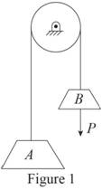
Write total length of cable connecting block A and block B.
Here,
Differentiate Equation (1) with respect to t to write velocity of the blocks.
Here,
Differentiate Equation (2) with respect to t to write acceleration of the blocks.
First of all check the required static friction with static friction to maintain equilibrium.
Sketch the free body diagram and kinetic diagram of block A as shown in Figure (2).
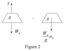
Refer Figure (2).
Consider downward direction as positive.
Apply Newton’s law of motion along y-axis.
Here, T is the tension in the cable,
Sketch the free body diagram and kinetic diagram of block B as shown in Figure (3).
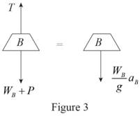
Refer Figure (3).
Consider downward direction as positive.
Apply Newton’s law of motion along y-axis.
Find the equation of acceleration of block A.
Here, T is the tension in the cable,
Substitute
The initial velocity of block A is zero.
Find the equation of velocity of block A using kinematics:
Here,
Substitute At
Find the equation of time required for block A to reach any velocity.
Find the acceleration of block A
Substitute 200 lb for
Therefore, the acceleration of block A for system 1 is
Find the acceleration of block A
Substitute 200 lb for
Therefore, the acceleration of block A for system 2 is
Find the acceleration of block A
Substitute 2200 lb for
Therefore, the acceleration of block A for system 2 is
(b)
Find the velocity of block A for each system after it has moved through 10 ft
(b)
Answer to Problem 12.15P
The velocity of block A for system 1 after it has moved through 10 ft is
The velocity of block A for system 2 after it has moved through 10 ft is
The velocity of block A for system 3 after it has moved through 10 ft is
Explanation of Solution
Calculation:
Find the velocity of block A for system 1
Substitute
Thus, the velocity of block A for system 1 after it has moved through 10 ft is
Find the velocity of block A for system 2
Substitute
Thus, the velocity of block A for system 2 after it has moved through 10 ft is
Find the velocity of block A for system 3
Substitute
Thus, the velocity of block A for system 3 after it has moved through 10 ft is
(c)
Find the time required for block A to reach a velocity of 20 ft/s
(c)
Answer to Problem 12.15P
The time required for block A for system 1 to reach a velocity of 20 ft/s is
The time required for block A for system 2 to reach a velocity of 20 ft/s is
The time required for block A for system 3 to reach a velocity of 20 ft/s is
Explanation of Solution
Calculation:
Find the time required for block A for system 1
Substitute
Thus, the time of required for block A for system 1 to reach a velocity of 20 ft/s is
Find the time required for block A for system 2
Substitute
Thus, the time of required for block A for system 2 to reach a velocity of 20 ft/s is
Find the time required for block A for system 3
Substitute
Thus, the time of required for block A for system 3 to reach a velocity of 20 ft/s is
Want to see more full solutions like this?
Chapter 12 Solutions
Vector Mechanics for Engineers: Statics and Dynamics


- CORRECT AND DETAILED SOLUTION WITH FBD ONLY. I WILL UPVOTE THANK YOU. CORRECT ANSWER IS ALREADY PROVIDED. I REALLY NEED FBD. The roof truss shown carries roof loads, where P = 10 kN. The truss is consisting of circular arcs top andbottom chords with radii R + h and R, respectively.Given: h = 1.2 m, R = 10 m, s = 2 m.Allowable member stresses:Tension = 250 MPaCompression = 180 MPa1. If member KL has square section, determine the minimum dimension (mm).2. If member KL has circular section, determine the minimum diameter (mm).3. If member GH has circular section, determine the minimum diameter (mm).ANSWERS: (1) 31.73 mm; (2) 35.81 mm; (3) 18.49 mmarrow_forwardPROBLEM 3.23 3.23 Under normal operating condi- tions a motor exerts a torque of magnitude TF at F. The shafts are made of a steel for which the allowable shearing stress is 82 MPa and have diameters of dCDE=24 mm and dFGH = 20 mm. Knowing that rp = 165 mm and rg114 mm, deter- mine the largest torque TF which may be exerted at F. TF F rG- rp B CH TE Earrow_forward1. (16%) (a) If a ductile material fails under pure torsion, please explain the failure mode and describe the observed plane of failure. (b) Suppose a prismatic beam is subjected to equal and opposite couples as shown in Fig. 1. Please sketch the deformation and the stress distribution of the cross section. M M Fig. 1 (c) Describe the definition of the neutral axis. (d) Describe the definition of the modular ratio.arrow_forward
- using the theorem of three moments, find all the moments, I only need concise calculations with minimal explanations. The correct answers are provided at the bottomarrow_forwardMechanics of materialsarrow_forwardusing the theorem of three moments, find all the moments, I need concise calculations onlyarrow_forward
- Can you provide steps and an explaination on how the height value to calculate the Pressure at point B is (-5-3.5) and the solution is 86.4kPa.arrow_forwardPROBLEM 3.46 The solid cylindrical rod BC of length L = 600 mm is attached to the rigid lever AB of length a = 380 mm and to the support at C. When a 500 N force P is applied at A, design specifications require that the displacement of A not exceed 25 mm when a 500 N force P is applied at A For the material indicated determine the required diameter of the rod. Aluminium: Tall = 65 MPa, G = 27 GPa. Aarrow_forwardFind the equivalent mass of the rocker arm assembly with respect to the x coordinate. k₁ mi m2 k₁arrow_forward
 Elements Of ElectromagneticsMechanical EngineeringISBN:9780190698614Author:Sadiku, Matthew N. O.Publisher:Oxford University Press
 Mechanics of Materials (10th Edition)Mechanical EngineeringISBN:9780134319650Author:Russell C. HibbelerPublisher:PEARSON
 Thermodynamics: An Engineering ApproachMechanical EngineeringISBN:9781259822674Author:Yunus A. Cengel Dr., Michael A. BolesPublisher:McGraw-Hill Education
 Control Systems EngineeringMechanical EngineeringISBN:9781118170519Author:Norman S. NisePublisher:WILEY
 Mechanics of Materials (MindTap Course List)Mechanical EngineeringISBN:9781337093347Author:Barry J. Goodno, James M. GerePublisher:Cengage Learning
 Engineering Mechanics: StaticsMechanical EngineeringISBN:9781118807330Author:James L. Meriam, L. G. Kraige, J. N. BoltonPublisher:WILEY