
EBK FUNDAMENTALS OF ELECTRIC CIRCUITS
6th Edition
ISBN: 8220102801448
Author: Alexander
Publisher: YUZU
expand_more
expand_more
format_list_bulleted
Concept explainers
Videos
Textbook Question
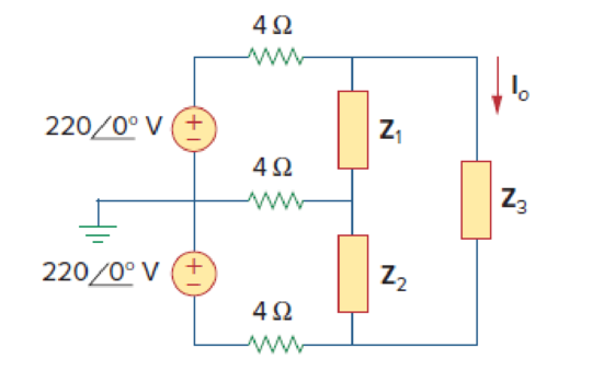
Chapter 12, Problem 60P
Use PSpice or MultiSim to determine Io in the single-phase, three-wire circuit of Fig. 12.66. Let Z1 = 15 – j10 Ω, Z2 = 30 + j20 Ω, and Z3 = 12 + j5 Ω.
Expert Solution & Answer
Want to see the full answer?
Check out a sample textbook solution
Students have asked these similar questions
Can be solve this problem without ai chatgpt .
Not use ai please
Draw the complete circular stator winding for a three
phase delta connected AC generator consisting of 4 poles
and 24 slots using a parallel connection. Your submission
must consist of two drawings as follows:
One drawing must show the winding arrangement of the
phasegroups in the slots of the stator highlighting the
start and finish of each phasegroup
The other drawing must show only the end connections of
each phase group for a parallel connection of the
phasegroups and a delta connection of the phases
The use of AutoCad or any other software is encouraged.
Chapter 12 Solutions
EBK FUNDAMENTALS OF ELECTRIC CIRCUITS
Ch. 12.2 - Given that Vbn=22030V, find Van and Vcn, assuming...Ch. 12.3 - A Y-connected balanced three-phase generator with...Ch. 12.4 - One line voltage of a balanced Y-connected source...Ch. 12.5 - A positive-sequence, balanced -connected source...Ch. 12.6 - In a balanced -Y circuit, Vab=44015 and ZY = (12 +...Ch. 12.7 - For the Y-Y circuit in Practice Prob. 12.2,...Ch. 12.7 - Calculate the line current required for a 30-kW...Ch. 12.7 - Assume that the two balanced loads in Fig....Ch. 12.8 - The unbalanced -load of Fig. 12.24 is supplied by...Ch. 12.8 - Find the line currents in the unbalanced...
Ch. 12.9 - Prob. 11PPCh. 12.9 - For the unbalanced circuit in Fig. 12.32, use...Ch. 12.10 - Repeat Example 12.13 for the network in Fig. 12.24...Ch. 12.10 - Let the line voltage VL = 208 V and the wattmeter...Ch. 12.10 - If the load in Fig. 12.35 is delta-connected with...Ch. 12 - What is the phase sequence of a three-phase motor...Ch. 12 - If in an acb phase sequence, , then Vcn is:Ch. 12 - Which of these is not a required condition for a...Ch. 12 - Prob. 4RQCh. 12 - Prob. 5RQCh. 12 - In a Y-Y system, a line voltage of 220 V produces...Ch. 12 - In a - system, a phase voltage of 100 V produces a...Ch. 12 - When a Y-connected load is supplied by voltages in...Ch. 12 - Prob. 9RQCh. 12 - Prob. 10RQCh. 12 - If Vab = 400 V in a balanced Y-connected...Ch. 12 - What is the phase sequence of a balanced...Ch. 12 - Given a balanced Y-connected three-phase generator...Ch. 12 - A three-phase system with abc sequence and VL =...Ch. 12 - For a Y-connected load, the time-domain...Ch. 12 - Using Fig. 12.41, design a problem to help other...Ch. 12 - Obtain the line currents in the three-phase...Ch. 12 - In a balanced three-phase Y-Y system, the source...Ch. 12 - A balanced Y-Y four-wire system has phase voltages...Ch. 12 - For the circuit in Fig. 12.43, determine the...Ch. 12 - In the Y- system shown in Fig. 12.44, the source...Ch. 12 - Using Fig. 12.45, design a problem to help other...Ch. 12 - In the balanced three-phase Y- system in Fig....Ch. 12 - Obtain the line currents in the three-phase...Ch. 12 - The circuit in Fig. 12.48 is excited by a balanced...Ch. 12 - A balanced delta-connected load has a phase...Ch. 12 - A positive sequence wye-connected source where ,...Ch. 12 - If Van = 22060 V in the network of Fig. 12.49,...Ch. 12 - For the - circuit of Fig. 12.50, calculate the...Ch. 12 - Prob. 20PCh. 12 - Three 440-V generators form a delta-connected...Ch. 12 - Find the line currents IaA, IbB, and IcC in the...Ch. 12 - A balanced delta connected source is connected to...Ch. 12 - A balanced delta-connected source has phase...Ch. 12 - In the circuit of Fig. 12.54, if , , , find the...Ch. 12 - Using Fig. 12.55, design a problem to help other...Ch. 12 - A -connected source supplies power to a...Ch. 12 - The line-to-line voltages in a Y-load have a...Ch. 12 - A balanced three-phase Y- system has V rms and Z =...Ch. 12 - In Fig. 12.56, the rms value of the line voltage...Ch. 12 - A balanced delta-connected load is supplied by a...Ch. 12 - Design a problem to help other students better...Ch. 12 - A three-phase source delivers 4.8 kVA to a...Ch. 12 - A balanced wye-connected load with a phase...Ch. 12 - Three equal impedances, 60 + j30 each, are...Ch. 12 - A 4200-V, three-phase transmission line has an...Ch. 12 - The total power measured in a three-phase system...Ch. 12 - Given the circuit in Fig. 12.57 below, find the...Ch. 12 - Find the real power absorbed by the load in Fig....Ch. 12 - For the three-phase circuit in Fig. 12.59, find...Ch. 12 - A balanced delta-connected load draws 5 kW at a...Ch. 12 - A balanced three-phase generator delivers 7.2 kW...Ch. 12 - Refer to Fig. 12.48. Obtain the complex power...Ch. 12 - A three-phase line has an impedance of 1 + j3 per...Ch. 12 - A balanced wye-connected load is connected to the...Ch. 12 - A three-phase load consists of three 100-...Ch. 12 - The following three parallel-connected three-phase...Ch. 12 - A balanced, positive-sequence wye-connected source...Ch. 12 - Each phase load consists of a 20- resistor and a...Ch. 12 - A balanced three-phase source with VL = 240 V rms...Ch. 12 - Consider the wye-delta system shown in Fig. 12.60....Ch. 12 - A four-wire wye-wye circuit has...Ch. 12 - Using Fig. 12.61, design a problem that will help...Ch. 12 - A balanced three-phase Y-source with VP = 880 V...Ch. 12 - A three-phase supply, with the line-to-line...Ch. 12 - Using Fig. 12.63, design a problem to help other...Ch. 12 - Determine the line currents for the three-phase...Ch. 12 - Solve Prob. 12.10 using PSpice or MultiSim. For...Ch. 12 - The source in Fig. 12.65 is balanced and exhibits...Ch. 12 - Use PSpice or MultiSim to determine Io in the...Ch. 12 - Given the circuit in Fig. 12.67, use PSpice or...Ch. 12 - Using Fig. 12.68, design a problem to help other...Ch. 12 - Use PSpice or MultiSim to find currents IaA and...Ch. 12 - For the circuit in Fig. 12.58, use PSpice or...Ch. 12 - A balanced three-phase circuit is shown in Fig....Ch. 12 - A three-phase, four-wire system operating with a...Ch. 12 - As shown in Fig. 12.72, a three-phase four-wire...Ch. 12 - Meter readings for a three-phase wye-connected...Ch. 12 - A certain store contains three balanced...Ch. 12 - The two-wattmeter method gives P1=1200W and...Ch. 12 - In Fig. 12.73, two wattmeters are properly...Ch. 12 - If wattmeters W1 and W2 are properly connected...Ch. 12 - For the circuit displayed in Fig. 12.74, find the...Ch. 12 - Predict the wattmeter readings for the circuit in...Ch. 12 - Prob. 75PCh. 12 - Show that the I2R losses will be higher for a...Ch. 12 - A three-phase generator supplied 10 kVA at a power...Ch. 12 - Prob. 78CPCh. 12 - A balanced three-phase generator has an abc phase...Ch. 12 - A balanced three-phase source furnishes power to...Ch. 12 - A professional center is supplied by a balanced...Ch. 12 - A balanced three-phase system has a distribution...Ch. 12 - A commercially available three-phase inductive...Ch. 12 - Figure 12.76 displays a three-phase...Ch. 12 - Design a three-phase heater with suitable...Ch. 12 - For the single-phase three-wire system in Fig....Ch. 12 - Consider the single-phase three-wire system shown...
Knowledge Booster


Learn more about
Need a deep-dive on the concept behind this application? Look no further. Learn more about this topic, electrical-engineering and related others by exploring similar questions and additional content below.Similar questions
- 1. For v(t)=2Σn-[8(t-n) + 28(t-n-0.4)], determine (a) (10%) a figure of v(t); (b) (5%) period To; (c) (10%) Fourier series in Form III; (d) (5%) Fourier transform; (e) (5%) total power.arrow_forward5. In the figure, v(t) = m(t)ej2nfct where the message signal is m(t): = Acos (2πfmt) and the carrier signal is vc(t) = 2e−j(2nfct+0) where 0 is constant and 0 < fmarrow_forward= cos (2π x 10t+ 0) where 0 is random with a probability density E [0, 2π), and f(0) = 0 otherwise. v,(t) passes through a linear filter below. 2. Consider a random process v(t) function f(0) = 1/(2) for vi(t)- H(f) vo(t) Determine (a) (5%) vo(t); (b) (10%) autocorrelation function of v(t); (c) (8%) power spectral density function of vo(t); (d) (7%) power of vo(t). 1 = H(f) 2πf2+1arrow_forward4. Consider v(t) = 2 cos(t) + 5 sin(2t) passes through a linear system with frequence response H(f). 3 vi(t) Determine (a) (10%) vo(t); (b) (5%) power of vo(t). H(f) → vo(t) H(f)= 3, Ifls- 4π (0, otherwise.arrow_forward3. For the AM demodulator in figure, v(t) = m(t)cos (2πfet + 4) with a constant where the message signal is m(t) v(t)- =Acos (2πfmt) and carrier signal is v(t) = cos (2πfet) with fmarrow_forwardNot use ai pleasearrow_forward14arrow_forward5. In the figure, v(t) = m(t)ej2nfct where the message signal is m(t): = Acos (2πfmt) and the carrier signal is vc(t) = 2e−j(2nfct+0) where 0 is constant and 0 < fmarrow_forwardFor the following parallel resonant bandpass filter, find the exact center frequency of the pass band and the bandwidth. Given: • Vin = 20 V • L = 7.5 μH C = 270 pF - Rw = 5.1 Q R₁ = 750 0 Center Frequency: f= kHz Bandwidth: BW= kHz Maximum Output Voltage: Vout(max)= V Minimum Output Voltage: Vout(min) = V 270 pF HH C ww L Rw 5.1Q 7.5 HH Vin 20 V RLoad 750 Ω Voutarrow_forward3. For v(t) = 4Σn=-8(t-n- 0.5), (a) (10%) draw a figure of v(t); (b) (5%) determine period To; (c) (10%) determine Fourier transform form III; (d) (5%) determine power spectral density.arrow_forward1. For v(t) = 2 cos(2π x 20t) + 3 sin (2π x 10t), determine (a) (5%) period To; →→T= (b) (8%) Fourier transform form II; (c) (5%) power of the fundamental frequency component; (d) (2%) total power. s [ue] dtarrow_forwardDesign, simulate and implement an electropneumatic automation system with PLC for 2 cylinders (A and B), which when pressing the push button S1 performs the following pneumatic sequence: A- B- B+ A+ for 10 seconds. With the push button S2 the sequence can be stopped at any time.arrow_forwardarrow_back_iosSEE MORE QUESTIONSarrow_forward_iosRecommended textbooks for you

 Power System Analysis and Design (MindTap Course ...Electrical EngineeringISBN:9781305632134Author:J. Duncan Glover, Thomas Overbye, Mulukutla S. SarmaPublisher:Cengage Learning
Power System Analysis and Design (MindTap Course ...Electrical EngineeringISBN:9781305632134Author:J. Duncan Glover, Thomas Overbye, Mulukutla S. SarmaPublisher:Cengage LearningCurrent Divider Rule; Author: Neso Academy;https://www.youtube.com/watch?v=hRU1mKWUehY;License: Standard YouTube License, CC-BY