
Concept explainers
Videos
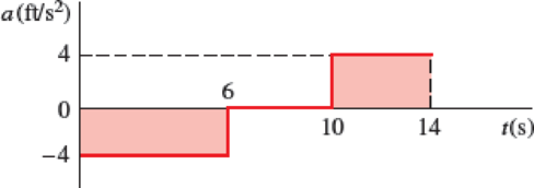
A particle moves in a straight line with a constant acceleration of −4 ft/s2 for 6 s, zero acceleration for the next 4 s, and a constant acceleration of +4 ft/s2 for the next 4 s. Knowing that the particle starts from the origin and that its velocity is −8 ft/s during the zero acceleration time interval, (a) construct the v−t and x−t curves for 0 ≤ t ≤ 14 s, (b) determine the position and the velocity of the particle and the total distance traveled when t = 14 s.
Fig. P11.61 and P11.62
(a)
Construct the
Explanation of Solution
Given information:
The constant acceleration
The acceleration is zero from 6sec to 10 sec.
From 10 sec to 14 sec the acceleration
The velocity
Calculation:
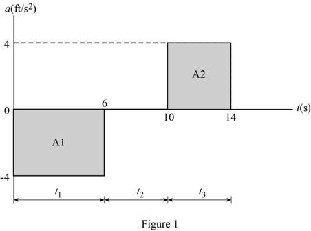
Show a-t curve of particle that moves in a straight line as in Figure (1).
Calculate the area
Substitute 6 sec for
Calculate the area
Substitute 4 sec for
Calculate the velocity
Substitute
Calculate the velocity
Substitute
Calculate the velocity
Substitute
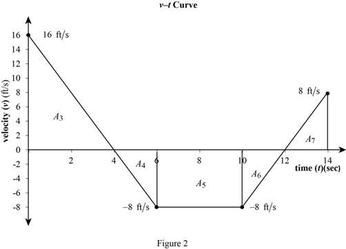
Tabulated the acceleration (a), velocity (v) corresponding to time (t) in Table (1) :
| t(s) | ||
| 0 | -4 | 16 |
| 6 | 0 | -8 |
| 10 | 0 | -8 |
| 14 | 4 | 8 |
Plot the v-t curve of particle that moves in a straight line with areas as in Figure (2).
Calculate the area
Here,
Substitute 4 sec for
Calculate the area
Here,
Substitute 2 sec for
Calculate the area
Here,
Substitute 4 sec for
Calculate the area
Here,
Substitute 2 sec for
Calculate the area
Here,
Substitute 4 sec for
Calculate the position
Calculate the position
Substitute 0 for
Calculate the position
Substitute
Calculate the position
Substitute
Calculate the position
Substitute
Calculate the position
Substitute
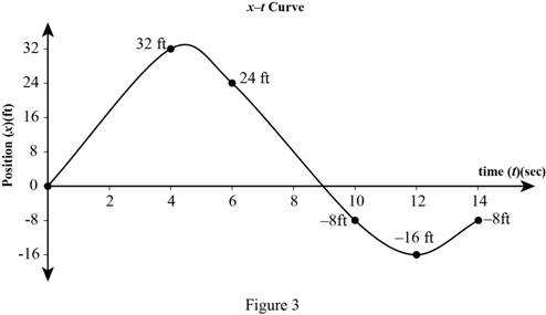
Tabulated the position (x) corresponding to time (t) in Table 2:
| t (sec) | x (ft) |
| 0 | 0 |
| 4 | 32 |
| 6 | 24 |
| 10 | -8 |
| 12 | -16 |
| 14 | -8 |
Plot x-t curve of particle that moves in a straight line with areas as in Figure 3.
(b)
The position, velocity of the particle and the total distance (d) traveled when time (t) 14 sec.
Answer to Problem 11.61P
The total distance (d) traveled when time (t) 14 sec is
Explanation of Solution
Given information:
The constant acceleration
The acceleration is zero from 6sec to 10 sec.
From 10 sec to 14 sec the acceleration
The velocity
Calculation:
Calculate the area
Substitute 6 sec for
Calculate the area
Substitute 4 sec for
Calculate the velocity
Substitute
Calculate the velocity
Substitute
Calculate the velocity
Substitute
Calculate the area
Here,
Substitute 4 sec for
Calculate the area
Here,
Substitute 2 sec for
Calculate the area
Here,
Substitute 4 sec for
Calculate the area
Here,
Substitute 2 sec for
Calculate the area
Here,
Substitute 4 sec for
Calculate the position
Calculate the position
Substitute 0 for
Calculate the position
Substitute
Calculate the position
Substitute
Calculate the position
Substitute
Calculate the position
Substitute
Calculate the distance
Substitute 0 for
Calculate the distance
Substitute
Calculate the distance
Substitute
Calculate the total distance (d) traveled when time (t) is 14 sec
Substitute
Therefore, the total distance (d) traveled when time (t) 14 sec is
Want to see more full solutions like this?
Chapter 11 Solutions
Vector Mechanics for Engineers: Statics and Dynamics


- from this problem a want you to help to draw the shear moment and the bending momentarrow_forwardreaction at a is 1.6 wL (pos) handwritten solutions only please. correct answers upvotedarrow_forward1 8 4 Add numbers so that the sum of any row or column equals .30 Use only these numbers: .1.2.3.4.5.6.10.11.12.12.13.14.14arrow_forward
- Uppgift 2 (9p) I77777 20 kN 10 kN/m 4 [m] 2 2 Bestäm tvärkrafts- och momentdiagram för balken i figuren ovan. Extrempunkter ska anges med både läge och värde i diagrammen.arrow_forward**Problem 8-45.** The man has a mass of 60 kg and the crate has a mass of 100 kg. If the coefficient of static friction between his shoes and the ground is \( \mu_s = 0.4 \) and between the crate and the ground is \( \mu_c = 0.3 \), determine if the man is able to move the crate using the rope-and-pulley system shown. **Diagram Explanation:** The diagram illustrates a scenario where a man is attempting to pull a crate using a rope-and-pulley system. The setup is as follows: - **Crate (C):** Positioned on the ground with a rope attached. - **Rope:** Connects the crate to a pulley system and extends to the man. - **Pulley on Tree:** The rope runs over a pulley mounted on a tree which redirects the rope. - **Angles:** - The rope between the crate and tree forms a \(30^\circ\) angle with the horizontal. - The rope between the tree and the man makes a \(45^\circ\) angle with the horizontal. - **Man (A):** Pulling on the rope with the intention of moving the crate. This arrangement tests the…arrow_forwardplease solve this problems follow what the question are asking to do please show me step by steparrow_forward
- please help me to solve this problem and determine the stress for each point i like to be explained step by step with the correct answerarrow_forwardplease solve this problem for me the best way that you can explained to solve please show me the step how to solvearrow_forwardplese solbe this problem and give the correct answer solve step by step find the forces and line actionarrow_forward
 Elements Of ElectromagneticsMechanical EngineeringISBN:9780190698614Author:Sadiku, Matthew N. O.Publisher:Oxford University Press
 Mechanics of Materials (10th Edition)Mechanical EngineeringISBN:9780134319650Author:Russell C. HibbelerPublisher:PEARSON
 Thermodynamics: An Engineering ApproachMechanical EngineeringISBN:9781259822674Author:Yunus A. Cengel Dr., Michael A. BolesPublisher:McGraw-Hill Education
 Control Systems EngineeringMechanical EngineeringISBN:9781118170519Author:Norman S. NisePublisher:WILEY
 Mechanics of Materials (MindTap Course List)Mechanical EngineeringISBN:9781337093347Author:Barry J. Goodno, James M. GerePublisher:Cengage Learning
 Engineering Mechanics: StaticsMechanical EngineeringISBN:9781118807330Author:James L. Meriam, L. G. Kraige, J. N. BoltonPublisher:WILEY