
Mechanics of Materials (10th Edition)
10th Edition
ISBN: 9780134319650
Author: Russell C. Hibbeler
Publisher: PEARSON
expand_more
expand_more
format_list_bulleted
Concept explainers
Videos
Textbook Question
thumb_up100%
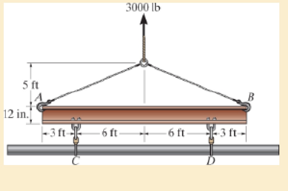
Chapter 11.2, Problem 11.6P
The allowable bending stress is σallow = 22 ksi and the allowable shear stress is τallow = 12 ksi.
Expert Solution & Answer
Want to see the full answer?
Check out a sample textbook solution
Students have asked these similar questions
A 2D incompressible flow has velocitycomponents u= X^2 - 2y^2 and v=aX^b y^c
,where a, b, and c are numbers.
Find the values of a, b, and c
Find the stream function
Please can you assist with the attached question please?
(a) Find a second-order homogeneous linear ODE for which the given functions are
solutions. (b) Show linear independence by the Wronskian. (c) Solve the initial value
problem.
a. cos(5x), sin(5x), y(0) = 3, y'(0) = −5
b. e-2.5x cos(0.3x), e-2.5x sin(0.3x), y(0) = 3, y'(0) = -7.5
Chapter 11 Solutions
Mechanics of Materials (10th Edition)
Ch. 11.2 - Determine the minimum dimension a to the nearest...Ch. 11.2 - of the rod to safely support the load. The rod is...Ch. 11.2 - The wood has an allowable normal stress of allow =...Ch. 11.2 - of the beam's cross section to safely support the...Ch. 11.2 - Determine the minimum dimension b to the nearest...Ch. 11.2 - The beam is made of steel having an allowable...Ch. 11.2 - Determine its dimensions if it is to be...Ch. 11.2 - Determine the minimum width of the beam to the...Ch. 11.2 - if P=10 kip.Ch. 11.2 - If the allowable bending stress is allow = 22 ksi...
Ch. 11.2 - The allowable bending stress is allow = 24 ksi and...Ch. 11.2 - The allowable bending stress is allow = 22 ksi and...Ch. 11.2 - The allowable bending stress is allow = 24 ksi and...Ch. 11.2 - Select the lightest-weight wide-flange beam from...Ch. 11.2 - The beam has an allowable normal stress of allow =...Ch. 11.2 - The beam has an allowable normal stress of allow...Ch. 11.2 - If each nail can support a shear force of 200 lb....Ch. 11.2 - If each beam is to be designed to carry 90 lb/ft...Ch. 11.2 - Determine its height h so that it simultaneously...Ch. 11.2 - The beam is constructed from four boards. If each...Ch. 11.2 - Prob. 11.15PCh. 11.2 - The beam has an allowable normal stress of allow....Ch. 11.2 - Determine the maximum cable force P that can...Ch. 11.2 - to safely support the load. The wood has an...Ch. 11.2 - and the wood has an allowable normal stress of...Ch. 11.2 - If the glue can support a shear stress of allow, =...Ch. 11.2 - If the allowable bending stress is allow = 6 MPa,...Ch. 11.2 - Determine the width b if the height h=2b.Ch. 11.2 - The allowable bending stress is allow = 24 ksi and...Ch. 11.2 - if allow = 30 ksi and allow = 15 ksi. The journal...Ch. 11.2 - if allow = 30 ksi and allow = 15 ksi. The journal...Ch. 11.2 - Select the lightest-weight wide-flange beam from...Ch. 11.2 - The allowable bending stress is allow = 30 ksi and...Ch. 11.2 - The allowable bending stress is allow = 30 ksi and...Ch. 11.2 - If the maximum bending stress is not to exceed...Ch. 11.2 - Determine the maximum load that can safely be...Ch. 11.4 - Determine the variation in the width was a...Ch. 11.4 - The tapered beam supports a uniform distributed...Ch. 11.4 - The tapered beam supports the concentrated force P...Ch. 11.4 - The beam is made from a plate that has a constant...Ch. 11.4 - Determine the variation in the depth d of a...Ch. 11.4 - Determine the variation of the radius r of the...Ch. 11.4 - Prob. 11.37PCh. 11.4 - Determine the variation in the width b as a...Ch. 11.4 - The tubular shaft has an inner diameter of 15 mm....Ch. 11.4 - Prob. 11.40PCh. 11.4 - Prob. 11.41PCh. 11.4 - The pulleys fixed to the shaft are loaded as...Ch. 11.4 - Prob. 11.43PCh. 11.4 - Prob. 11.44PCh. 11.4 - Prob. 11.45PCh. 11 - The cantilevered beam has a circular cross...Ch. 11 - Select the lightest-weight wide-flange overhanging...Ch. 11 - Prob. 11.3RPCh. 11 - Determine the shaft's diameter to the nearest...Ch. 11 - Select the lightest-weight wide-flange beam from...Ch. 11 - The simply supported joist is used in the...Ch. 11 - The simply supported joist is used in the...Ch. 11 - by 4-in. pieces of wood braced as shown. If the...
Additional Engineering Textbook Solutions
Find more solutions based on key concepts
Comprehension Check 7-14
The power absorbed by a resistor can be given by P = I2R, where P is power in units of...
Thinking Like an Engineer: An Active Learning Approach (4th Edition)
The job of the _____ is to fetch instructions, carry out the operations commanded by the instructions, and prod...
Starting Out With Visual Basic (8th Edition)
Why is the study of database technology important?
Database Concepts (8th Edition)
This optional Google account security feature sends you a message with a code that you must enter, in addition ...
SURVEY OF OPERATING SYSTEMS
17–1C A high-speed aircraft is cruising in still air. How does the temperature of air at the nose of the aircra...
Thermodynamics: An Engineering Approach
How are relationships between tables expressed in a relational database?
Modern Database Management
Knowledge Booster


Learn more about
Need a deep-dive on the concept behind this application? Look no further. Learn more about this topic, mechanical-engineering and related others by exploring similar questions and additional content below.Similar questions
- Solve the IVP. a. y" 16y 17e* ; = y(0) = 6, y'(0) = -2 b. (D² + 41)y = sin(t) + ½ sin(3t) + sin(t) ; y(0) = 0, y'(0) : = 35 31arrow_forwardFind the general solution. a. y' 5y = 3ex - 2x + 1 - b. y" +4y' + 4y = e¯*cos(x) c. (D² + I)y = cos(wt), w² # 1arrow_forwardhandwritten solutions, please!!arrow_forward
- > Homework 4 - Spring 2025.pdf Spring 2025.pdf k 4 - Spring 2025.pdf (447 KB) Due: Thursday, February 27 Page 1 > of 2 ZOOM 1. A simply supported shaft is shown in Figure 1 with wo = 25 N/cm and M = 20 N cm. Use singularity functions to determine the reactions at the supports. Assume EI = 1000 kN cm². M Wo 0 10 20 30 40 50 60 70 80 90 100 110 cm Figure 1 - Problem 1 2. A support hook was formed from a rectangular bar. Find the stresses at the inner and outer surfaces at sections just above and just below O-B. 210 mmarrow_forwardA distillation column with a total condenser and a partial reboiler is separating ethanol andwater at 1.0 atm. Feed is 0.32 mol fraction ethanol and it enters as a saturated liquid at 100mol/s on the optimum plate. The distillate product is a saturated liquid with 80 mol% ethanol.The condenser removes 5615 kW. The bottoms product is 0.05 mol fraction ethanol. AssumeCMO is valid.(a) Find the number of equilibrium stages for this separation. [6 + PR](b) Find how much larger the actual reflux ratio, R, used is than Rmin, i.e. R/Rmin. [3]Note: the heats of vaporization of ethanol and water are λe = 38.58 and λw = 40.645 arrow_forwardWe have a feed that is a binary mixture of methanol and water (60.0 mol% methanol) that issent to a system of two flash drums hooked together. The vapor from the first drum is cooled,which partially condenses the vapor, and then is fed to the second flash drum. Both drumsoperate at 1.0 atm and are adiabatic. The feed to the first drum is 1000 kmol/hr. We desire aliquid product from the first drum that is 35.0 mol% methanol. The second drum operates at afraction vaporized of (V/F)2 = 0.25.(a) Find the liquid flow rate leaving the first flash drum, L1 (kmol/hr). [286 kmol/hr](b) Find the vapor composition leaving the second flash drum, y2. [0.85]arrow_forward
- = The steel curved bar shown has rectangular cross-section with a radial height h = 6 mm and thickness b = 4mm. The radius of the centroidal axis is R = 80 mm. A force P = 10 N is applied as shown. Assume the steel modulus of 207,000 MPa and G = 79.3(103) MPa, repectively. elasticity and shear modulus E = Find the vertical deflection at point B. Use Castigliano's method for a curved flexural member and since R/h > 10, neglect the effect of shear and axial load, thereby assuming that deflection is due to merely the bending moment. Note the inner and outer radii of the curves bar are: r = 80 + ½ (6) = 83 mm, r₁ = 80 − ½ (6) = 77 mm 2 2 Sπ/2 sin² 0 d = √π/² cos² 0 d0 = Π 0 4 大 C R B Parrow_forwardThe steel eyebolt shown in the figure is loaded with a force F = 75 lb. The eyebolt is formed from round wire of diameter d = 0.25 in to a radius R₁ = 0.50 in in the eye and at the shank. Estimate the stresses at the inner and outer surfaces at section A-A. Notice at the section A-A: r₁ = 0.5 in, ro = 0.75 in rc = 0.5 + 0.125 = 0.625 in Ri 200 F FAarrow_forwardI have the fallowing question and solution from a reeds naval arc book. Im just confused as to where this answer came from and the formulas used. Wondering if i could have this answer/ solution broken down and explained in detail. A ship of 7000 tonne displacement has a waterplane areaof 1500 m2. In passing from sea water into river water of1005 kg/m3 there is an increase in draught of 10 cm. Find the Idensity of the sea water. picture of the "answer" is attachedarrow_forward
- Problem A2 long steel tube has a rectangular cross-section with outer dimensions of 20 x 20 mm and a uniform wall thickness of 2. The tube is twisted along its length with torque, T. The tube material is 1045 CD steel with shear yield strength of S,, =315 MPa. Assume shear modulus, G = 79.3GPa. (a) Estimate the maximum torque that can be applied without yielding (b) Estimate the torque required to produce 5 degrees total angle of twist over the length of the tube. (c) What is the maximum torque that can be applied without yielding, if a solid rectangular shaft with dimensions of 20 x 20 is used? You may use the exact solution.arrow_forwardA simply supported beam is loaded as shown. Considering symmetry, the reactions at supports A and B are R₁ = R₂ = wa 2 Using the singularity method, determine the shear force V along the length of the beam as a function of distance x from the support A. A B Ir. 2a За W C R₁₂ x 2. Using the singularity method, determine the bending M along the length of the beam as a function of distance x, from the support A. 3. Using the singularity method, determine the beam slope and deflection along the length of the beam as a function of the distance x, from the support A. Assume the material modulus of elasticity, E and the moment of inertia of the beam cross-section, I are given.arrow_forwardA steel tube, 2 m long, has a rectangular cross-section with outer dimensions of 20 × 30 mm and a uniform wall thickness of 1 mm. The tube is twisted along its length with torque, T. The tube material is 1018 CD steel with shear yield strength of Ssy =185 MPa. Assume shear modulus, G = 79.3GPa. (a) Estimate the maximum torque that can be applied without yielding.- (b) Estimate the torque required to produce 3 degrees total angle of twist over the length of the tube. (c) What is the maximum torque that can be applied without yielding, if a solid rectangular shaft with dimensions of 20 x 30 mm is used? You may use the exact solution:arrow_forward
arrow_back_ios
SEE MORE QUESTIONS
arrow_forward_ios
Recommended textbooks for you
 Mechanics of Materials (MindTap Course List)Mechanical EngineeringISBN:9781337093347Author:Barry J. Goodno, James M. GerePublisher:Cengage Learning
Mechanics of Materials (MindTap Course List)
Mechanical Engineering
ISBN:9781337093347
Author:Barry J. Goodno, James M. Gere
Publisher:Cengage Learning
Everything About COMBINED LOADING in 10 Minutes! Mechanics of Materials; Author: Less Boring Lectures;https://www.youtube.com/watch?v=N-PlI900hSg;License: Standard youtube license