
Mechanics of Materials (10th Edition)
10th Edition
ISBN: 9780134319650
Author: Russell C. Hibbeler
Publisher: PEARSON
expand_more
expand_more
format_list_bulleted
Concept explainers
Videos
Textbook Question
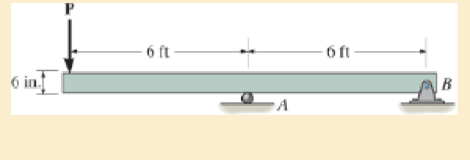
Chapter 11.2, Problem 11.3P
if P=10 kip.
Expert Solution & Answer

Trending nowThis is a popular solution!

Students have asked these similar questions
Design and assemble on the fluidsim (or a draft) the Hydraulic Drive Circuit, with the following characteristics:
(a) Sequential operation, pressure, for the advance and return of the cylinders (according to the proper operation for the device) controlled by a directional 4x3 way, closed center;
(b) Speed control for the cylinders, according to the load signal;
(c) Pressure counterbalance for cylinder A, in order to compensate for the weight of the assembly.
This is an old exam practice question. The answer is Pmax = 218.8 kN normal stress governs but why?
Moist air initially at T₁ = 140°C, p₁ = 4 bar, and p₁ = 50% is contained in a 2.0-m³ closed, rigid tank. The tank contents are cooled to T₂
35°C.
Step 1
Determine the temperature at which condensation begins, in °C.
Chapter 11 Solutions
Mechanics of Materials (10th Edition)
Ch. 11.2 - Determine the minimum dimension a to the nearest...Ch. 11.2 - of the rod to safely support the load. The rod is...Ch. 11.2 - The wood has an allowable normal stress of allow =...Ch. 11.2 - of the beam's cross section to safely support the...Ch. 11.2 - Determine the minimum dimension b to the nearest...Ch. 11.2 - The beam is made of steel having an allowable...Ch. 11.2 - Determine its dimensions if it is to be...Ch. 11.2 - Determine the minimum width of the beam to the...Ch. 11.2 - if P=10 kip.Ch. 11.2 - If the allowable bending stress is allow = 22 ksi...
Ch. 11.2 - The allowable bending stress is allow = 24 ksi and...Ch. 11.2 - The allowable bending stress is allow = 22 ksi and...Ch. 11.2 - The allowable bending stress is allow = 24 ksi and...Ch. 11.2 - Select the lightest-weight wide-flange beam from...Ch. 11.2 - The beam has an allowable normal stress of allow =...Ch. 11.2 - The beam has an allowable normal stress of allow...Ch. 11.2 - If each nail can support a shear force of 200 lb....Ch. 11.2 - If each beam is to be designed to carry 90 lb/ft...Ch. 11.2 - Determine its height h so that it simultaneously...Ch. 11.2 - The beam is constructed from four boards. If each...Ch. 11.2 - Prob. 11.15PCh. 11.2 - The beam has an allowable normal stress of allow....Ch. 11.2 - Determine the maximum cable force P that can...Ch. 11.2 - to safely support the load. The wood has an...Ch. 11.2 - and the wood has an allowable normal stress of...Ch. 11.2 - If the glue can support a shear stress of allow, =...Ch. 11.2 - If the allowable bending stress is allow = 6 MPa,...Ch. 11.2 - Determine the width b if the height h=2b.Ch. 11.2 - The allowable bending stress is allow = 24 ksi and...Ch. 11.2 - if allow = 30 ksi and allow = 15 ksi. The journal...Ch. 11.2 - if allow = 30 ksi and allow = 15 ksi. The journal...Ch. 11.2 - Select the lightest-weight wide-flange beam from...Ch. 11.2 - The allowable bending stress is allow = 30 ksi and...Ch. 11.2 - The allowable bending stress is allow = 30 ksi and...Ch. 11.2 - If the maximum bending stress is not to exceed...Ch. 11.2 - Determine the maximum load that can safely be...Ch. 11.4 - Determine the variation in the width was a...Ch. 11.4 - The tapered beam supports a uniform distributed...Ch. 11.4 - The tapered beam supports the concentrated force P...Ch. 11.4 - The beam is made from a plate that has a constant...Ch. 11.4 - Determine the variation in the depth d of a...Ch. 11.4 - Determine the variation of the radius r of the...Ch. 11.4 - Prob. 11.37PCh. 11.4 - Determine the variation in the width b as a...Ch. 11.4 - The tubular shaft has an inner diameter of 15 mm....Ch. 11.4 - Prob. 11.40PCh. 11.4 - Prob. 11.41PCh. 11.4 - The pulleys fixed to the shaft are loaded as...Ch. 11.4 - Prob. 11.43PCh. 11.4 - Prob. 11.44PCh. 11.4 - Prob. 11.45PCh. 11 - The cantilevered beam has a circular cross...Ch. 11 - Select the lightest-weight wide-flange overhanging...Ch. 11 - Prob. 11.3RPCh. 11 - Determine the shaft's diameter to the nearest...Ch. 11 - Select the lightest-weight wide-flange beam from...Ch. 11 - The simply supported joist is used in the...Ch. 11 - The simply supported joist is used in the...Ch. 11 - by 4-in. pieces of wood braced as shown. If the...
Additional Engineering Textbook Solutions
Find more solutions based on key concepts
A nozzle at A discharges water with an initial velocity of 36 ft/s at an angle with the horizontal. Determine ...
Vector Mechanics For Engineers
Why is the study of database technology important?
Database Concepts (8th Edition)
17–1C A high-speed aircraft is cruising in still air. How does the temperature of air at the nose of the aircra...
Thermodynamics: An Engineering Approach
How are relationships between tables expressed in a relational database?
Modern Database Management
The following C++ program will not compile because the lines have been mixed up. cout Success\n; cout Success...
Starting Out with C++ from Control Structures to Objects (9th Edition)
The job of the _____ is to fetch instructions, carry out the operations commanded by the instructions, and prod...
Starting Out With Visual Basic (8th Edition)
Knowledge Booster


Learn more about
Need a deep-dive on the concept behind this application? Look no further. Learn more about this topic, mechanical-engineering and related others by exploring similar questions and additional content below.Similar questions
- Air at T₁ = 24°C, p₁ = 1 bar, 50% relative humidity enters an insulated chamber operating at steady state with a mass flow rate of 3 kg/min and mixes with a saturated moist air stream entering at T2=7°C, p₂ = 1 bar. A single mixed stream exits at T3-17°C, p3=1 bar. Neglect kinetic and potential energy effectsarrow_forwardHand calculation of cooling loadarrow_forwardAn HEV has a 24kW battery. How many miles can it go on electricity alone at 40 mph on a flat straight road with no headwind? Assume the rolling resistance factor is 0.018 and the Coefficient of Drag (aerodynamic) is 0.29 the frontal area is 2.25m^2 and the vehicle weighs 1618 kg.arrow_forward
- As shown in the figure below, moist air at T₁ = 36°C, 1 bar, and 35% relative humidity enters a heat exchanger operating at steady state with a volumetric flow rate of 10 m³/min and is cooled at constant pressure to 22°C. Ignoring kinetic and potential energy effects, determine: (a) the dew point temperature at the inlet, in °C. (b) the mass flow rate of moist air at the exit, in kg/min. (c) the relative humidity at the exit. (d) the rate of heat transfer from the moist air stream, in kW. (AV)1, T1 P₁ = 1 bar 11 = 35% 120 T₂=22°C P2 = 1 bararrow_forwardThe inside temperature of a wall in a dwelling is 19°C. If the air in the room is at 21°C, what is the maximum relative humidity, in percent, the air can have before condensation occurs on the wall?arrow_forwardThe inside temperature of a wall in a dwelling is 19°C. If the air in the room is at 21°C, what is the maximum relative humidity, in percent, the air can have before condensation occurs on the wall?arrow_forward
- ###arrow_forwardFind the closed loop transfer function and then plot the step response for diFerentvalues of K in MATLAB. Show step response plot for different values of K. Auto Controls Show solution for transform function and provide matlab code (use k(i) for for loop NO COPIED SOLUTIONSarrow_forwardThis is an old practice exam. The answer is Ta-a = 4.615 MPa max = 14.20 MPa Su = 31.24 MPa Sus = 10.15 MPa but why?arrow_forward
- This is an old practice exam. The answer is dmin = 42.33 mm but how?arrow_forward5.) 12.124* - Block B (WB = 12 lb) rests as shown on the upper surface of wedge A (W₁ = 30 lb). The angle of the slope is 0 = 30°. Neglect friction, and find immediately after the system is released from rest (a) the acceleration of a (a) and (b) the acceleration of B relative to A (a B/A).arrow_forwardWhat is the Maximum Bending Moment induced in the following Beam, if? P = 19 KN L = 11 m Ensure that your answer is in kN.m. لا اللهarrow_forward
arrow_back_ios
SEE MORE QUESTIONS
arrow_forward_ios
Recommended textbooks for you
 International Edition---engineering Mechanics: St...Mechanical EngineeringISBN:9781305501607Author:Andrew Pytel And Jaan KiusalaasPublisher:CENGAGE L
International Edition---engineering Mechanics: St...
Mechanical Engineering
ISBN:9781305501607
Author:Andrew Pytel And Jaan Kiusalaas
Publisher:CENGAGE L
Stresses Due to Fluctuating Loads Introduction - Design Against Fluctuating Loads - Machine Design 1; Author: Ekeeda;https://www.youtube.com/watch?v=3FBmQXfP_eE;License: Standard Youtube License