
Videos
A refrigerator operating on the vapor-compression refrigeration cycle using refrigerant-134a as the refrigerant is considered. The temperatures of the cooled space and the ambient air are at 10°F and 80°F, respectively. R-134a enters the compressor at 20 psia as a saturated vapor and leaves at 140 psia and 160°F. The refrigerant leaves the condenser as a saturated liquid. The rate of cooling provided by the system is 45,000 Btu/h. Determine (a) the mass flow rate of R-134a and the COP, (b) the exergy destruction in each component of the cycle and the second-law efficiency of the compressor, and (c) the second-law efficiency of the cycle and the total exergy destruction in the cycle.
(a)
The mass flow rate of R-134a and the COP.
Answer to Problem 33P
The mass flow rate of R-134a and the COP is
Explanation of Solution
Show the T-s diagram for vapor-compression refrigeration cycle as in Figure (1).
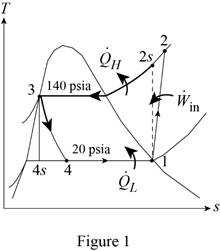
From Figure (1), write the specific enthalpy at state 3 is equal to state 4 due to throttling process.
Here, specific enthalpy at state 3 and 4 is
Express the work input.
Here, specific enthalpy at state 2 and 1 is
Express heat supplied to the cooled space.
Express the heat removed from the cooled space.
Express quality at state 4.
Here, specific enthalpy at saturated liquid and evaporation and
Express specific entropy at state 4.
Here, specific entropy at saturated liquid and evaporation and
Express mass flow rate of R-134a.
Here, rate of heat lost is
Express the COP of the cycle.
Conclusion:
Refer Table A-12E, “saturated refrigerant-134a-pressure table”, and write the properties corresponding to initial pressure
Here, specific entropy at state 1 is
Refer Table A-13E, “superheated refrigerant-134a”, and write the properties corresponding to pressure at state 2
Here, specific entropy at state 2 is
Refer Table A-12E, “saturated refrigerant-134a-pressure table”, and write the properties corresponding to pressure at state 3
Here, specific entropy at state 3 is
As specific enthalpy at state 3 is equal to specific enthalpy at state 4,
Refer Table A-12E, “saturated refrigerant-134a-pressure table”, and write the properties corresponding to pressure at state 4
Substitute
Substitute
Substitute
Substitute
Substitute
Substitute
Substitute
Hence, the mass flow rate of R-134a and the COP is
(b)
The exergy destruction in each component of the cycle and the second-law efficiency of the compressor.
Answer to Problem 33P
The exergy destruction in compressor is
Explanation of Solution
For compressor:
Express the exergy destruction in compressor.
Here, surrounding temperature is
For condenser:
Express the exergy destruction in condenser.
Here, entropy generation during process 2-3 is
For expansion valve:
For evaporator:
Express the exergy destruction in evaporator.
Here, entropy generation during process 4-1 is
Express the power input of the compressor.
Express second law efficiency of the compressor.
Conclusion:
Perform unit conversion of surrounding temperature from
Perform unit conversion of high temperature medium from
Perform unit conversion of low temperature medium from
Substitute
Hence, the exergy destruction in compressor is
Substitute
Hence, the exergy destruction in condenser is
Substitute
Hence, the exergy destruction in expansion valve is
Substitute
Hence, the exergy destruction in evaporator is
Substitute
Substitute
Hence, the second-law efficiency of the compressor is
(c)
The second-law efficiency of the cycle and the total exergy destruction in the cycle.
Answer to Problem 33P
The second-law efficiency of the cycle is
Explanation of Solution
Express the exergy of the heat transferred from the low temperature medium.
Determine the second law efficiency of the cycle.
Express the total exergy destruction in the cycle.
Conclusion:
Substitute
Substitute
Hence, the second-law efficiency of the cycle is
Substitute
Hence, the total exergy destruction in the cycle is
Want to see more full solutions like this?
Chapter 11 Solutions
Thermodynamics: An Engineering Approach


- Consider a large 6-cm-thick stainless steel plate (k = 15.1 W/m-K) in which heat is generated uniformly at a rate of 5 × 10⁵ W/m³. Both sides of the plate are exposed to an environment at 30°C with a heat transfer coefficient of 60 W/m²K. Determine the value of the highest and lowest temperature. The highest temperature is The lowest temperature is °C. °C.arrow_forwardSketch and explain a PV Diagram and a Temperature Entropy Diagram for a 4 stroke diesel engine please, please explain into detail the difference bewteen the two and referance the a diagram. Please include a sketch or an image of each diagramarrow_forwardDraw left view of the first orthographic projectionarrow_forward
- Sketch and Describe a timing diagram for a 2 stroke diesel engine emphasis on the 2 stroke as my last answer explained 4 stroke please include a diagram or sketch.arrow_forwardA 4 ft 200 Ib 1000 Ib.ft C 2 ft 350 Ib - за в 2.5 ft 150 Ib 250 Ib 375 300 Ib Replace the force system acting on the frame. shown in the figure by a resultant force (magnitude and direction), and specify where its line of action intersects member (AB), measured from point (A).arrow_forwardA continuous flow calorimeter was used to obtain the calorific value of a sample of fuel and the following data collected: Mass of fuel: 2.25 kgInlet water temperature: 11 ° COutlet water temperature 60 ° CQuantity of water: 360 Liters Calorimeter efficiency: 85%Calculate the calorific value of the sample ( kJ / kg ). ive submitted this question twice and have gotten two way different answers. looking for some help thanksarrow_forward
- 15 kg of steel ball bearings at 100 ° C is immersed in 25 kg of water at 20 ° C . Assuming no loss of heat to or from the container, calculate the final temperature of the water after equilibrium has been attained.Specific heat of steel: 0.4857 kJ / kg / ° KSpecific heat of water: 4.187 kJ / kg / ° Karrow_forwardSketch and explain a PV Diagram and a Temperature Entropy Diagram for a 4 stroke diesel enginearrow_forwardA continuous flow calorimeter was used to obtain the calorific value of a sample of fuel and the following data collected: Mass of fuel: 2.25 kgInlet water temperature: 11 ° COutlet water temperature 60 ° CQuantity of water: 360 Liters Calorimeter efficiency: 85%Calculate the calorific value of the sample ( kJ / kg ).arrow_forward
- Chapter 12 - Lecture Notes.pptx: (MAE 272-01) (SP25) DY... Scoresarrow_forwardmylabmastering.pearson.com Chapter 12 - Lecture Notes.pptx: (MAE 272-01) (SP25) DY... P Pearson MyLab and Mastering Scoresarrow_forwardanswer the fallowing Brake Specific Fuel Consumption - 0.3 kg/kwh, Mechanical Efficiency- 90% Calorific Value of Fuel -45 MJ/kg. Given these values, find the indicated power, indicated thermal efficiency and brake thermal efficiencyarrow_forwardarrow_back_iosSEE MORE QUESTIONSarrow_forward_iosRecommended textbooks for you
 Refrigeration and Air Conditioning Technology (Mi...Mechanical EngineeringISBN:9781305578296Author:John Tomczyk, Eugene Silberstein, Bill Whitman, Bill JohnsonPublisher:Cengage Learning
Refrigeration and Air Conditioning Technology (Mi...Mechanical EngineeringISBN:9781305578296Author:John Tomczyk, Eugene Silberstein, Bill Whitman, Bill JohnsonPublisher:Cengage Learning