
Videos
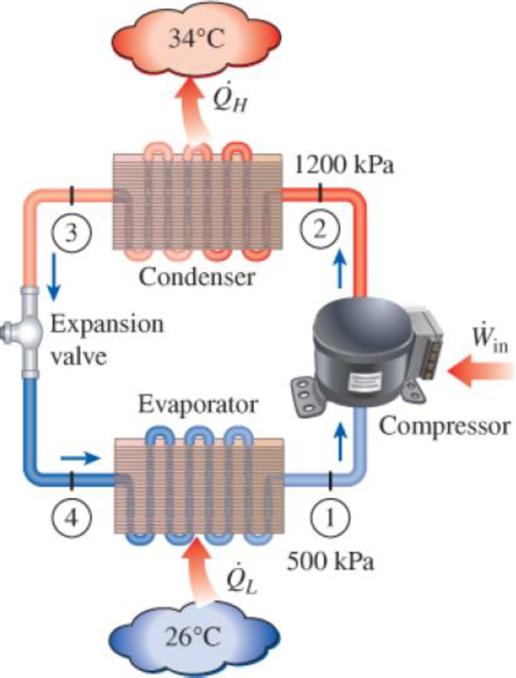
An air conditioner with refrigerant-134a as the working fluid is used to keep a room at 26°C by rejecting the waste heat to the outside air at 34°C. The room is gaining heat through the walls and the windows at a rate of 250 kJ/min while the heat generated by the computer, TV, and lights amounts to 900 W. An unknown amount of heat is also generated by the people in the room. The condenser and evaporator pressures are 1200 and 500 kPa, respectively. The refrigerant is saturated liquid at the condenser exit and saturated vapor at the compressor inlet. If the refrigerant enters the compressor at a rate of 100 L/min and the isentropic efficiency of the compressor is 75 percent, determine (a) the temperature of the refrigerant at the compressor exit, (b) the rate of heat generation by the people in the room, (c) the COP of the air conditioner, and (d) the minimum volume flow rate of the refrigerant at the compressor inlet for the same compressor inlet and exit conditions.
FIGURE P11–115
(a)
The temperature of the refrigerant at the compressor exit.
Answer to Problem 115RP
The temperature of the refrigerant at the compressor exit is
Explanation of Solution
Show the T-s diagram as in Figure (1).
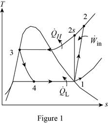
From Figure (1), write the specific enthalpy at state 3 is equal to state 4 due to throttling process.
Here, specific enthalpy at state 3 and 4 is
Express the specific enthalpy at state 2.
Here, specific enthalpy at state 2s is
Conclusion:
Perform the unit conversion of pressure at state 1 from
Refer Table A-13, “superheated refrigerant-134a”, and write the properties corresponding to pressure of
Here, specific enthalpy, volume and entropy is
Perform the unit conversion of pressure at state 2 from
Refer Table A-12, “saturated refrigerant-134a-pressure table”, and write the specific enthalpy at state 3 corresponding to pressure at state 3 of
Here, specific enthalpy at saturated liquid is
Substitute
Refer Table A-13, “superheated refrigerant 134a”, and write the specific enthalpy at state 2s corresponding to pressure at state 2 of
Write the formula of interpolation method of two variables.
Here, the variables denote by x and y is specific entropy at state 2 and specific enthalpy at state 2 respectively.
Show the specific enthalpy at state 2s corresponding to specific entropy as in Table (1).
|
Specific entropy at state 2 |
Specific enthalpy at state 2s |
| 0.9132 | 273.92 |
| 0.9242 | |
| 0.9268 | 278.28 |
Substitute
Thus, the specific enthalpy at state 2s is,
Substitute
Refer Table A-13, “superheated refrigerant 134a”, and write the temperature at state 2 corresponding to pressure at state 2 of
Show the temperature at state 2 corresponding to specific enthalpy at state 2 as in Table (2).
|
Specific enthalpy at state 2s |
Temperature at state 2 |
| 278.28 | 50 |
| 283.48 | |
| 289.66 | 60 |
Use excels and tabulates the values form Table (2) in Equation (III) to get,
Hence, the temperature of the refrigerant at the compressor exit is
(b)
The rate of heat generation by the people in the room.
Answer to Problem 115RP
The rate of heat generation by the people in the room is
Explanation of Solution
Express the mass flow rate of the refrigerant.
Here, volume flow rate at state 1 is
Express the refrigeration load.
Express the rate of heat generation by the people in the room.
Here, rate of heat generated is
Conclusion:
Substitute
Substitute
Substitute
Hence, the rate of heat generation by the people in the room is
(c)
The COP of the air conditioner.
Answer to Problem 115RP
The COP of the air conditioner is
Explanation of Solution
Express the rate of work input.
Express the coefficient of performance of the air conditioner.
Conclusion:
Substitute
Substitute
Hence, the COP of the air conditioner is
(d)
The minimum volume flow rate of the refrigerant at the compressor inlet.
Answer to Problem 115RP
The minimum volume flow rate of the refrigerant at the compressor inlet is
Explanation of Solution
Express the reversible coefficient of performance of the cycle.
Here, high and low temperature medium is
Express corresponding minimum power input.
Express the minimum mass flow rate.
Express the minimum volume flow rate of the refrigerant at the compressor inlet
Conclusion:
Substitute
Substitute
Substitute
Substitute
Hence, the minimum volume flow rate of the refrigerant at the compressor inlet is
Want to see more full solutions like this?
Chapter 11 Solutions
Thermodynamics: An Engineering Approach


- Mych CD 36280 kg. 0.36 givens Tesla truck frailer 2017 Model Vven 96154kph ronge 804,5km Cr Powertrain Across PHVAC rwheel 0.006 0.88 9M² 2 2kW 0.55M ng Zg Prated Trated Pair 20 0.95 1080 kW 1760 Nm 1,2 determine the battery energy required to meet the range when fully loaded determine the approximate time for the fully-loaded truck-trailor to accelerate from 0 to 60 mph while Ignoring vehicle load forcesarrow_forward12-217. The block B is sus- pended from a cable that is at- tached to the block at E, wraps around three pulleys, and is tied to the back of a truck. If the truck starts from rest when ID is zero, and moves forward with a constant acceleration of ap = 0.5 m/s², determine the speed of the block at D the instant x = 2 m. Neglect the size of the pulleys in the calcu- lation. When xƊ = 0, yc = 5 m, so that points C and D are at the Prob. 12-217 5 m yc =2M Xparrow_forwardsolve both and show matlab code auto controlsarrow_forward
- 12-82. The roller coaster car trav- els down the helical path at con- stant speed such that the paramet- ric equations that define its posi- tion are x = c sin kt, y = c cos kt, z = h - bt, where c, h, and b are constants. Determine the mag- nitudes of its velocity and accelera- tion. Prob. 12-82 Narrow_forwardGiven: = refueling Powertran SOURCE EMISSIONS vehide eff eff gasoline 266g co₂/kwh- HEV 0.90 0.285 FLgrid 411ilg Co₂/kWh 41111gCo₂/kWh EV 0.85 0.80 Production 11x10% og CO₂ 13.7 x 10°g CO₂ A) Calculate the breakeven pont (in km driven) for a EV against on HEV in Florida of 0.1kWh/kM Use a drive cycle conversion 5) How efficient would the powertrain of the HEV in this example have to be to break even with an EV in Florida after 150,000 Miles of service (240,000) km Is it plausible to achieve the answer from pert b Consideans the HaXINERY theoretical efficiency of the Carnot cycle is 5020 and there are additional losses of the transMISSION :- 90% efficiency ? c A what do you conclude is the leading factor in why EVs are less emissive than ICE,arrow_forwardsolve autocontrolsarrow_forward
- Problem 3.21P: Air at 100F(38C) db,65F(18C) wb, and sea-level pressure is humidified adiabatically with steam. The steam supplied contains 20 percent moisture(quality of 0.80) at 14.7psia(101.3kpa). The air is humidified to 60 percent relative humidity. Find the dry bulb temperature of the humidified air using (a)chart 1a or 1b and (b) the program PSYCH.arrow_forwardPUNTO 4. calculate their DoF using Gruebler's formula. PUNTO 5. Groundarrow_forwardPUNTO 2. PUNTO 3. calculate their DoF using Gruebler's formula. III IAarrow_forward
- calculate their DoF using Gruebler's formula. PUNTO 6. PUNTO 7. (Ctrl)arrow_forwardA pump delivering 230 lps of water at 30C has a 300-mm diameter suction pipe and a 254-mm diameter discharge pipe as shown in the figure. The suction pipe is 3.5 m long and the discharge pipe is 23 m long, both pipe's materials are cast iron. The water is delivered 16m above the intake water level. Considering head losses in fittings, valves, and major head loss. a) Find the total dynamic head which the pump must supply. b)It the pump mechanical efficiency is 68%, and the motor efficiency is 90%, determine the power rating of the motor in hp.given that: summation of K gate valve = 0.25check valve=390 degree elbow= 0.75foot valve= 0.78arrow_forwardA pump delivering 230 lps of water at 30C has a 300-mm diameter suction pipe and a 254-mm diameter discharge pipe as shown in the figure. The suction pipe is 3.5 m long and the discharge pipe is 23 m long, both pipe's materials are cast iron. The water is delivered 16m above the intake water level. Considering head losses in fittings, valves, and major head loss. a) Find the total dynamic head which the pump must supply. b)It the pump mechanical efficiency is 68%, and the motor efficiency is 90%, determine the power rating of the motor in hp.arrow_forward
 Refrigeration and Air Conditioning Technology (Mi...Mechanical EngineeringISBN:9781305578296Author:John Tomczyk, Eugene Silberstein, Bill Whitman, Bill JohnsonPublisher:Cengage Learning