Videos
Reconsider Prob. 10–83. Determine which components of the combined cycle are the most wasteful of work potential.
10–83 A combined gas–steam power cycle uses a simple gas turbine for the topping cycle and simple Rankine cycle for the bottoming cycle. Atmospheric air enters the gas turbine at 101 kPa and 20°C, and the maximum gas cycle temperature is 1100°C. The compressor pressure ratio is 8; the compressor isentropic efficiency is 85 percent; and the gas turbine isentropic efficiency is 90 percent. The gas stream leaves the heat exchanger at the saturation temperature of the steam flowing through the heat exchanger. Steam flows through the heat exchanger with a pressure of 6000 kPa and leaves at 320°C. The steam-cycle condenser operates at 20 kPa, and the isentropic efficiency of the steam turbine is 90 percent. Determine the mass flow rate of air through the air compressor required for this system to produce 100 MW of power. Use constant specific heats for air at room temperature.
Which component of the combined cycle is the most wasteful of work potential.
Answer to Problem 85P
The combustor of the gas-steam cycle has largest exergy destruction
Explanation of Solution
Show the
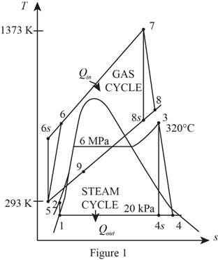
Refer Figure 1.
Consider the gas cycle (topping cycle) and their respective process states such as 5, 6,
Write the temperature and pressure relation at isentropic state and for the process 5-6-
Here, the temperature is
Write the formula for isentropic efficiency of compressor for the process 5-6-
Here, the enthalpy is
Rearrange and rewrite the equation (II) to obtain
Write the temperature and pressure relation at isentropic state and for the process 7-8-
Write the formula for isentropic efficiency of gas turbine
Rearrange and rewrite the equation (V) to obtain
At state 9: (heat exchanger)
The temperature
Refer Table A-5, “Saturated water-Pressure table”.
The saturation temperature corresponding to the pressure of
Refer Figure 1.
Consider the steam cycle (bottoming cycle) and their respective process states such as 1, 2, 3, 4,
At state 1:
The water exits the condenser as a saturated liquid at the pressure of
Refer Table A-5, “Saturated water-Pressure table”.
The enthalpy
At state 2:
Write the formula for work done by the pump during process 1-2.
Here, the specific volume is
Write the formula for enthalpy
At state 3: (Turbine inlet)
The steam enters the turbine as superheated vapour.
Refer Table A-6, “Superheated water”.
The enthalpy
From Figure 1,
At state 4: (Turbine exit or condenser inlet)
The steam exits the condenser as a saturated liquid at the pressure of
The quality of water at the exit of the turbine is expressed as follows.
The enthalpy at state
Here, the enthalpy is
Refer Table A-5, “Saturated water-Pressure table”.
Obtain the following properties corresponding to the pressure of
Write the formula for isentropic efficiency of the steam turbine
Rearrange the Equation (XI) to obtain the enthalpy
Write the formula for net work output of the gas cycle.
Here, the specific heat of air at constant pressure is
Write the formula for net work output of the steam cycle.
Write the general energy rate balance equation.
Here, the rate of energy in is
Consider the heat exchanger operates on steady state. Hence, the rate of change in net energy of the system is zero.
The Equation (XV) is reduced as follows for the heat exchanger.
Here, the mass flow rate of air is
Write the formula for mass flow rate of air through the compressor.
Write the formula for the exergy destruction for the process 3-4 (turbine).
Write the formula for the exergy destruction for the process 4-1 (condenser).
Write the formula for the exergy destruction for heat exchanger.
Write the formula for the exergy destruction for the process 5-6 (compressor).
Write the formula for the exergy destruction for the process 6-7 (combustion chamber).
Write the formula for the exergy destruction for the process 7-8 (gas turbine).
Here, the specific heat at constant pressure of air is
Refer Table A-2, “Ideal-gas specific heats of various common gases”.
The specific heat at constant pressure
Conclusion:
Substitute
Substitute
Substitute
Substitute
Substitute
Substitute
Here,
Substitute
Substitute
Equation (X).
Substitute
Substitute
Substitute
Equation (XIV).
Substitute
When, the mass flow rate of air is
Substitute
Thus, the Equation (XXIV) describes that
Substitute
Thus, the mass flow rate of the air through the air compressor required for this system to produce
Substitute
Consider the process 1 to 2 (Pump).
Here, the pump is isentropic. Hence the exergy destruction during the process 1-2 is zero.
Consider the process 3 to 4 (steam turbine).
Here,
Substitute
Thus, the exergy destruction during process 3-4 is
Substitute
Substitute
Substitute
Substitute
Substitute
The calculated exergy destruction value is greater for component combustor that is
Hence, the combustor of the gas-steam cycle has largest exergy destruction of all other components and that is the most wasteful of work potential.
Want to see more full solutions like this?
Chapter 10 Solutions
THERMODYNAMICS (LL)-W/ACCESS >CUSTOM<
Additional Engineering Textbook Solutions
Automotive Technology: Principles, Diagnosis, And Service (6th Edition) (halderman Automotive Series)
Starting Out With Visual Basic (8th Edition)
Starting Out with Programming Logic and Design (5th Edition) (What's New in Computer Science)
Java How to Program, Early Objects (11th Edition) (Deitel: How to Program)
Mechanics of Materials (10th Edition)
Java: An Introduction to Problem Solving and Programming (8th Edition)


- The link lengths and the value of 2 and offset for some fourbar crank-slide linkages are defined in Table 1. The linkage configuration and terminology are shown in Figure 1. For the rows assigned, find (a) all possible solutions for angle & and slider position d by vector loop method. (b) the transmission angle corresponding to angle 03. (Hint: Treat the vector R4 as virtual rocker) Show your work in details: vector loop, vector equations, solution procedure. Table 1 Row Link 2 Link 3 Offset Ө a 1.4 4 1 45° b 3 8 2 -30° C 5 20 -5 225° 03 slider axis B X offset Link 2 A R3 Link 3 R4 04 R2 02 R1 d Figure 1. Xarrow_forward4. Two links made of heat treated 6061 aluminum (Sy = 276 MPa, Sys = 160 MPa) are pinned together using a steel dowel pin (Sy = 1398 MPa, Sys = 806 MPa) as shown below. The links are to support a load P with a factor of safety of at least 2.0. Determine if the link will fail first by tearout, direct shear of the pin, bearing stress on the link, or tensile stress at section AA. (Hint: find the load P for each case and choose the case that gives the smallest load.) P 8 mm P 8 mm ¡+A 3 mm →A 10 mm Parrow_forward1. For a feature other than a sphere, circularity is where: A. The axis is a straight line B. The modifier is specified with a size dimension C. All points of the surface intersected by any plane perpendicular to an axis or spine (curved line) are equidistant from that axis or spine D. All points of the surface intersected by any plane passing through a common center are equidistant from that center 2. What type of variation is limited by a circularity toler- ance zone? A. Ovality B. Tapering C. Bending D. Warping 3. How does the Rule #1 boundary affect the application of a circularity tolerance? A. The modifier must be used. B. The feature control frame must be placed next to the size dimension. C. The circularity tolerance value must be less than the limits of size tolerance. D. Circularity cannot be applied where a Rule #1 boundary exists. 4. A circularity tolerance may use a modifier. A. Ø B. F C. M D. ℗ 5. A real-world application for a circularity tolerance is: A. Assembly (i.e.,…arrow_forward
- 3. A steel bar is pinned to a vertical support column by a 10 mm diameter hardened dowel pin, Figure 1. For P = 7500 N, find: a. the shear stress in the pin, b. the direct bearing stress on the hole in the bar, c. the minimum value of d to prevent tearout failure if the steel bar has a shear strength of 175 MPa. support column pin bar thickness of bar = 8 mm h d 150 mmarrow_forwardA press that delivers 115 strokes per minute, each stroke providing a force of 7826 N throughout a distance of 18 mm. The press efficiency is 90% and is driven by a 1749-rpm motor. Determine average torque that must be provided by the motor in the units of N-m.arrow_forward·3) find the force (P) for the figures (1) and (2) 15cm 10cm 15 h=10mm h2=6mm // Call = 90 N/2 P Agate Fig (i) Ans: 1)P=112614N 2) P=1956.5 N 25cm 25 cm الفترة أو الحجم تمر بالتي عثر اكو تورشن (ک Fig (2) h₁ = 10mm 42=6mm Cmarrow_forward
- 3. A steam power plant has an average monthly net power delivery of 740 MW over the course of a year. This power delivery is accomplished by burning coal in the boiler. The coal has a heating value of 9150 Btu/lbm. The cost of the coal is $14.20/ton. The overall thermal efficiency of the plant is, nth = Wnet Qboiler = 0.26 = 26% Determine the annual cost of the coal required to deliver the given average monthly power.arrow_forward47 14 16 12 34 10 12 12 33arrow_forward= The forces F₁ = 590 lb, F₂ = 380 lb, F3 = 240 lb and F 330 lb. Determine the forces in each member of the truss. Use positive values to indicate tension and negative values to indicate compression. a a a D b F₁ A 000 B. 779977 F₂V H G E F4 b BY NC SA 2013 Michael Swanbom Values for dimensions on the figure are given in the following table. Note the figure may not be to scale. Variable Value a 6 ft b 10.1 ft The force in member AB is lb. The force in member AH is lb. The force in member GH is lb. The force in member BH is lb. The force in member BC is lb. The force in member BG is lb. The force in member EG is lb. The force in member CD is lb. The force in member DE is lb. The force in member CE is lb. The force in member CG is lb.arrow_forward
 Elements Of ElectromagneticsMechanical EngineeringISBN:9780190698614Author:Sadiku, Matthew N. O.Publisher:Oxford University Press
 Mechanics of Materials (10th Edition)Mechanical EngineeringISBN:9780134319650Author:Russell C. HibbelerPublisher:PEARSON
 Thermodynamics: An Engineering ApproachMechanical EngineeringISBN:9781259822674Author:Yunus A. Cengel Dr., Michael A. BolesPublisher:McGraw-Hill Education
 Control Systems EngineeringMechanical EngineeringISBN:9781118170519Author:Norman S. NisePublisher:WILEY
 Mechanics of Materials (MindTap Course List)Mechanical EngineeringISBN:9781337093347Author:Barry J. Goodno, James M. GerePublisher:Cengage Learning
 Engineering Mechanics: StaticsMechanical EngineeringISBN:9781118807330Author:James L. Meriam, L. G. Kraige, J. N. BoltonPublisher:WILEY