(a)
The mass flow rate of air in the gas-turbine cycle.
(a)
Answer to Problem 109RP
The mass flow rate of air in the gas-turbine cycle is
Explanation of Solution
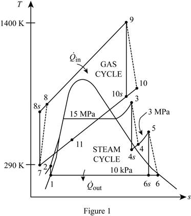
Show the T-s diagram as in Figure (1).

Express Prandtl number at state 8s.
Here, pressure at state 8s is
Express enthalpy at state 8.
Here, enthalpy at state 7 is
Express Prandtl number at state 10s.
Here, pressure at state 10s is
Express enthalpy at state 10.
Here, enthalpy at state 9 is
Express enthalpy at state 1.
Here, enthalpy of saturation liquid at pressure of
Express specific volume at state 1.
Here, specific volume of saturation liquid at pressure of
Express initial work input.
Here, pressure at state 2 and 1 is
Express enthalpy at state 2.
Express quality at state 4s.
Here, entropy at state 4s is
Express enthalpy at state 4s.
Here, enthalpy at saturation liquid and evaporation at pressure of
Express enthalpy at state 4.
Here, enthalpy at state 3 is
Express quality at state 6s.
Here, entropy at state 6s is
Express enthalpy at state 6s.
Here, enthalpy at saturation liquid and evaporation at pressure of
Express enthalpy at state 6.
Here, enthalpy at state 5 is
Express the mass flow rate of air in the gas-turbine cycle from energy balance equation.
Here, enthalpy at state 10 is
Conclusion:
Refer Table A-17, “ideal gas properties of air”, and write the enthalpy at state 7 and Prandtl number at state 7 corresponding to temperature at state 7 of
Substitute
Refer Table A-17, “ideal gas properties of air”, and write the enthalpy at state 8s corresponding to Prandtl number at state 8s of
Write the formula of interpolation method of two variables.
Here, the variables denote by x and y is Prandtl number at state8s and enthalpy at state 8s respectively.
Show the enthalpy at state 8s corresponding to Prandtl number as in Table (1).
|
Prandtl number at state 8s |
Enthalpy at state 8s |
| 9.684 | 523.63 |
| 9.849 | |
| 10.37 | 533.98 |
Substitute
Thus, enthalpy at state 8s corresponding to Prandtl number at state 8s of
Substitute
Refer Table A-17, “ideal gas properties of air”, and write the enthalpy at state 9 and Prandtl number at state 9 corresponding to temperature at state 9 of
Here, enthalpy at state 9 is
Substitute
Refer Table A-17, “ideal gas properties of air”, and write the enthalpy at state 10s corresponding to Prandtl number at state 10s of
Show the enthalpy at state 10s corresponding to Prandtl number as in Table (2).
|
Prandtl number at state 10s |
Enthalpy at state 10s |
| 52.59 | 843.98 |
| 56.3 | |
| 57.60 | 866.08 |
Use excels and substitutes the values from Table (II) in Equation (XVI) to get,
Here, enthalpy at state 10s is
Substitute
Refer Table A-17, “ideal gas properties of air”, and write the enthalpy at state 11 corresponding to temperature at state 11 of
Here, enthalpy at state 11 is
Refer Table A-5, “saturated water-pressure table”, and write the properties at pressure of
Substitute
Substitute
Substitute
Substitute
Refer Table A-6, “superheated water”, and write the properties corresponding to pressure at state 3 of
Here, enthalpy and entropy at state 3 is
Due to throttling process, entropy at state 3 is equal to entropy at state 4s.
Refer Table A-5, “saturated water-pressure table”, and write the properties corresponding to pressure of
Substitute
Substitute
Substitute
Refer Table A-6, “superheated water”, and write the properties corresponding to pressure at state 5 of
Here, enthalpy and entropy at state 5 is
Due to throttling process, entropy at state 5 is equal to entropy at state 6s.
Refer Table A-5, “saturated water-pressure table”, and write the properties corresponding to pressure of
Substitute
Substitute
Substitute
Substitute
Hence, the mass flow rate of air in the gas-turbine cycle is
(b)
The rate of total heat input.
(b)
Answer to Problem 109RP
The rate of total heat input is
Explanation of Solution
Express the rate of total heat input.
Conclusion:
Substitute
Hence, the rate of total heat input is
(c)
The thermal efficiency of the combined cycle.
(c)
Answer to Problem 109RP
The thermal efficiency of the combined cycle is
Explanation of Solution
Express the rate of total heat output.
Express the thermal efficiency of the combined cycle.
Conclusion:
Substitute
Substitute
Hence, the thermal efficiency of the combined cycle is
Want to see more full solutions like this?
Chapter 10 Solutions
THERMODYNAMICS (LL)-W/ACCESS >CUSTOM<
- Consider a steam power plant that operates on a simple, ideal Rankine cycle and has a net power output of 45 MW. Steam enters the turbine at 7 MPa and 500°C and is cooled in the condenser at a pressure of 10 kPa by running cooling water from a lake through the tubes of the condenser at a rate of 2000 kg/s. Show the cycle on a T-s diagram with respect to saturation lines, and determine The thermal efficiency of the cycle,The mass flow rate of the steam and the temperature rise of the cooling waterarrow_forwardTwo reversible heat engines operate in series between a source at 600°C, and a sink at 30°C. If the engines have equal efficiencies and the first rejects 400 kJ to the second, calculate: the temperature at which heat is supplied to the second engine, The heat taken from the source; and The work done by each engine. Assume each engine operates on the Carnot cyclearrow_forwardA steam turbine operates at steady state with inlet conditions of P1 = 5 bar, T1 = 320°C. Steam leaves the turbine at a pressure of 1 bar. There is no significant heat transfer between the turbine and its surroundings, and kinetic and potential energy changes between inlet and exit are negligible. If the isentropic turbine efficiency is 75%, determine the work developed per unit mass of steam flowing through the turbine, in kJ/kgarrow_forward
- Homework#5arrow_forwardMember AB has the angular velocity wAB = 2.5 rad/s and angular acceleration a AB = 9 rad/s². (Figure 1) Determine the magnitude of the velocity of point C at the instant shown. Determine the direction of the velocity of point C at the instant shown. Determine the magnitude of the acceleration of point C at the instant shown. Determine the direction of the acceleration of point C at the instant shown. A 300 mm WAB α AB B 500 mm 0=60° y 200 mmarrow_forwardYou are asked to design a unit to condense ammonia. The required condensation rate is 0.09kg/s. Saturated ammonia at 30 o C is passed over a vertical plate (10 cm high and 25 cm wide).The properties of ammonia at the saturation temperature of 30°C are hfg = 1144 ́10^3 J/kg andrv = 9.055 kg/m 3 . Use the properties of liquid ammonia at the film temperature of 20°C (Ts =10 o C):Pr = 1.463 rho_l= 610.2 kf/m^3 liquid viscosity= 1.519*10^-4 kg/ ms kinematic viscosity= 2.489*10^-7 m^2/s Cpl= 4745 J/kg C kl=0.4927 W/m Ca)Calculate the surface temperature required to achieve the desired condensation rate of 0.09 kg/s( should be 688 degrees C) b) Show that if you use a bigger vertical plate (2.5 m-wide and 0.8 m-height), the requiredsurface temperature would be now 20 o C. You may use all the properties given as an initialguess. No need to iterate to correct for Tf. c) What if you still want to use small plates because of the space constrains? One way to getaround this problem is to use small…arrow_forwardIf you have a spring mass damper system, given by m*x_double_dot + c*x_dot + kx = 0 where m, c, k (all positive scalars) are the mass, damper coefficient, and spring coefficient, respectively. x ∈ R represents the displacement of the mass. Let us then discuss the stability of the system by using Lyapunov stability theorem. Consider the system energy as a candidate Lyapunov function shown in the image. Discuss the positive definiteness of V (x, x_dot). Derive the Lyapunov rate of this system (i.e., V_dot ), and discuss the stability property of thesystem based on the information we gain from ̇V_dot .arrow_forwardIn class, two approaches—Theorems 1 and 2 below—are discussed to prove asymptotic stability of asystem when ̇V = 0. Show the asymptotic stability of the system given in Eq. (1) by applying Theorem 1. Show the asymptotic stability of the system given in Eq. (1) by applying Theorem 2.arrow_forwardHomework#5arrow_forwardarrow_back_iosSEE MORE QUESTIONSarrow_forward_iosRecommended textbooks for you
 Elements Of ElectromagneticsMechanical EngineeringISBN:9780190698614Author:Sadiku, Matthew N. O.Publisher:Oxford University Press
 Mechanics of Materials (10th Edition)Mechanical EngineeringISBN:9780134319650Author:Russell C. HibbelerPublisher:PEARSON
 Thermodynamics: An Engineering ApproachMechanical EngineeringISBN:9781259822674Author:Yunus A. Cengel Dr., Michael A. BolesPublisher:McGraw-Hill Education
 Control Systems EngineeringMechanical EngineeringISBN:9781118170519Author:Norman S. NisePublisher:WILEY
 Mechanics of Materials (MindTap Course List)Mechanical EngineeringISBN:9781337093347Author:Barry J. Goodno, James M. GerePublisher:Cengage Learning
 Engineering Mechanics: StaticsMechanical EngineeringISBN:9781118807330Author:James L. Meriam, L. G. Kraige, J. N. BoltonPublisher:WILEY
 Elements Of ElectromagneticsMechanical EngineeringISBN:9780190698614Author:Sadiku, Matthew N. O.Publisher:Oxford University Press
 Mechanics of Materials (10th Edition)Mechanical EngineeringISBN:9780134319650Author:Russell C. HibbelerPublisher:PEARSON
 Thermodynamics: An Engineering ApproachMechanical EngineeringISBN:9781259822674Author:Yunus A. Cengel Dr., Michael A. BolesPublisher:McGraw-Hill Education
 Control Systems EngineeringMechanical EngineeringISBN:9781118170519Author:Norman S. NisePublisher:WILEY
 Mechanics of Materials (MindTap Course List)Mechanical EngineeringISBN:9781337093347Author:Barry J. Goodno, James M. GerePublisher:Cengage Learning
 Engineering Mechanics: StaticsMechanical EngineeringISBN:9781118807330Author:James L. Meriam, L. G. Kraige, J. N. BoltonPublisher:WILEY