International Edition---engineering Mechanics: Statics 4th Edition
4th Edition
ISBN: 9781305856240
Author: Pytel
Publisher: Cengage
expand_more
expand_more
format_list_bulleted
Videos
Textbook Question
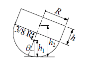
Chapter 10, Problem 10.44P
The body shown is a composite of a hemisphere and a cylinder, with both of uniform weight density
Expert Solution & Answer
Want to see the full answer?
Check out a sample textbook solution
Students have asked these similar questions
4. The rod ABCD is made of an aluminum for which E = 70 GPa. For the loading
shown, determine the deflection of (a) point B, (b) point D.
1.75 m
Area = 800 mm²
100 kN
B
1.25 m
с
Area = 500 mm²
75 kN
1.5 m
D
50 kN
Research and select different values for the R ratio from various engine models, then analyze how these changes affect instantaneous velocity and acceleration, presenting your findings visually using graphs.
Qu. 7 The v -t graph of a car while travelling along a road is shown. Draw the s -t and a -t graphs for the motion.
I need to draw a graph and I need to show all work step by step please do not get short cut from dtna
Chapter 10 Solutions
International Edition---engineering Mechanics: Statics 4th Edition
Ch. 10 - Determine the number of DOF for each of the...Ch. 10 - The uniform bar of weight W is held in equilibrium...Ch. 10 - Bars AB and AC of the mechanism are homogenous...Ch. 10 - The weight of each homogeneous bar of the linkage...Ch. 10 - The 1800-kg boat is suspended from two parallel...Ch. 10 - The 2.4-kg lamp, with center of gravity located at...Ch. 10 - The linkage is made of two homogenous bars of...Ch. 10 - For the frame shown, find the horizontal component...Ch. 10 - The four-bar linkage supports the homogeneous box...Ch. 10 - Prob. 10.10P
Ch. 10 - Determine the ratio P/Q of the forces that are...Ch. 10 - Find the vertical force P that will hold the...Ch. 10 - The linkage of the braking system consists of the...Ch. 10 - The automatic drilling robot must sustain a thrust...Ch. 10 - Determine the couple C for which the mechanism...Ch. 10 - The scissors jack is used to elevate the weight W....Ch. 10 - Prob. 10.17PCh. 10 - Calculate the torque C0 that must be applied to...Ch. 10 - Determine the force F and the angle a required to...Ch. 10 - Locate the instant center of rotation of bar AB...Ch. 10 - Prob. 10.21PCh. 10 - Determine the force P that will keep the mechanism...Ch. 10 - Prob. 10.23PCh. 10 - Prob. 10.24PCh. 10 - Prob. 10.25PCh. 10 - Determine the ratio P/Q for which the linkage will...Ch. 10 - Prob. 10.27PCh. 10 - Prob. 10.28PCh. 10 - If the input force to the compound lever is P = 30...Ch. 10 - Determine the roller reaction at F due to the...Ch. 10 - Prob. 10.31PCh. 10 - Prob. 10.32PCh. 10 - Prob. 10.33PCh. 10 - Prob. 10.34PCh. 10 - Prob. 10.35PCh. 10 - For the pliers shown, determine the relationship...Ch. 10 - When activated by the force P, the gripper cm a...Ch. 10 - Prob. 10.38PCh. 10 - The hinge is of the type used on some automobiles,...Ch. 10 - The spring attached to the sliding collar is...Ch. 10 - The weight W is suspended from end B of the...Ch. 10 - The uniform bar of weight W and length L = 1.8R...Ch. 10 - A slender homogeneous bar is bent into a right...Ch. 10 - The body shown is a composite of a hemisphere and...Ch. 10 - Prob. 10.45PCh. 10 - The uniform bar AB of weight W and length L is...Ch. 10 - Uniform rods of weights W1 and W2 are welded to...Ch. 10 - Prob. 10.48PCh. 10 - The semi-cylinder of radius r is placed on a...Ch. 10 - Prob. 10.50PCh. 10 - The spring attached to the homogenous bar of...Ch. 10 - The spring is connected to a rope that passes over...Ch. 10 - Find the equilibrium positions of the 30-lb...Ch. 10 - The mechanism of negligible weight supports the...Ch. 10 - Solve Prob. 10.54 assuming that A and B are...Ch. 10 - The stiffness of the ideal spring that is...Ch. 10 - Find the stable equilibrium position of the system...Ch. 10 - The uniform bar AB of weight W = kL is in...Ch. 10 - The weight of the uniform bar AB is W. The...Ch. 10 - The weightless bars AB and CE, together with the...Ch. 10 - Prob. 10.61PCh. 10 - The bar ABC is supported by three identical, ideal...
Knowledge Booster


Learn more about
Need a deep-dive on the concept behind this application? Look no further. Learn more about this topic, mechanical-engineering and related others by exploring similar questions and additional content below.Similar questions
- An unpressurized cylindrical tank with a 100-foot diameter holds a 40-foot column of water. What is total force acting against the bottom of the tank?arrow_forward7. In the following problems check to see if the set S is a vector subspace of the corresponding R. If it is not, explain why not. If it is, then find a basis and the dimension. (a) S = (b) S = {[],+,"} X1 x12x2 = x3 CR³ {[1], 4+4 = 1} CR³ X2arrow_forwardAAA Show laplace transform on 1; (+) to L (y(+)) : SY(s) = x (0) Y(s) = £ [lx (+)] = 5 x(+) · est de 2 -St L [ y (^) ] = So KG) et de D 2 D D AA Y(A) → Y(s) Ŷ (+) → s Y(s) -yarrow_forward
- 1) In each of the following scenarios, based on the plane of impact (shown with an (n, t)) and the motion of mass 1, draw the direction of motion of mass 2 after the impact. Note that in all scenarios, mass 2 is initially at rest. What can you say about the nature of the motion of mass 2 regardless of the scenario? m1 15 <+ m2 2) y "L χ m1 m2 m1 בז m2 Farrow_forward8. In the following check to see if the set S is a vector subspace of the corresponding Rn. If it is not, explain why not. If it is, then find a basis and the dimension. X1 (a) S = X2 {[2], n ≤ n } c X1 X2 CR² X1 (b) S X2 = X3 X4 x1 + x2 x3 = 0arrow_forward2) Suppose that two unequal masses m₁ and m₂ are moving with initial velocities V₁ and V₂, respectively. The masses hit each other and have a coefficient of restitution e. After the impact, mass 1 and 2 head to their respective gaps at angles a and ẞ, respectively. Derive expressions for each of the angles in terms of the initial velocities and the coefficient of restitution. m1 m2 8 m1 ↑ บา m2 ñ Вarrow_forward
- The fallowing question is from a reeds book on applied heat i am studying. Although the answer is provided, im struggling to understand the whole answer and the formulas and the steps theyre using. Also where some ov the values such as Hg and Hf come from in part i for example. Please explain step per step in detail thanks In an NH, refrigerator, the ammonia leaves the evaporatorand enters the cornpressor as dry saturated vapour at 2.68 bar,it leaves the compressor and enters the condenser at 8.57 bar with50" of superheat. it is condensed at constant pressure and leavesthe condenser as saturated liquid. If the rate of flow of the refrigerantthrough the circuit is 0.45 kglmin calculate (i) the compressorpower, (ii) the heat rejected to the condenser cooling water in kJ/s,an (iii) the refrigerating effect in kJ/s. From tables page 12, NH,:2.68 bar, hg= 1430.58.57 bar, hf = 275.1 h supht 50" = 1597.2Mass flow of refrigerant--- - - 0.0075 kgls 60Enthalpy gain per kg of refrigerant in…arrow_forwardstate the formulas for calculating work done by gasarrow_forwardExercises Find the solution of the following Differential Equations 1) y" + y = 3x² 3) "+2y+3y=27x 5) y"+y=6sin(x) 7) y"+4y+4y = 18 cosh(x) 9) (4)-5y"+4y = 10 cos(x) 11) y"+y=x²+x 13) y"-2y+y=e* 15) y+2y"-y'-2y=1-4x³ 2) y"+2y' + y = x² 4) "+y=-30 sin(4x) 6) y"+4y+3y=sin(x)+2 cos(x) 8) y"-2y+2y= 2e* cos(x) 10) y+y-2y=3e* 12) y"-y=e* 14) y"+y+y=x+4x³ +12x² 16) y"-2y+2y=2e* cos(x)arrow_forward
- The state of stress at a point is σ = -4.00 kpsi, σy = 16.00 kpsi, σ = -14.00 kpsi, Try = 11.00 kpsi, Tyz = 8.000 kpsi, and T = -14.00 kpsi. Determine the principal stresses. The principal normal stress σ₁ is determined to be [ The principal normal stress σ2 is determined to be [ The principal normal stress σ3 is determined to be kpsi. kpsi. The principal shear stress 71/2 is determined to be [ The principal shear stress 7½ is determined to be [ The principal shear stress T₁/, is determined to be [ kpsi. kpsi. kpsi. kpsi.arrow_forwardRepeat Problem 28, except using a shaft that is rotatingand transmitting a torque of 150 N * m from the left bearing to the middle of the shaft. Also, there is a profile keyseat at the middle under the load. (I want to understand this problem)arrow_forwardProb 2. The material distorts into the dashed position shown. Determine the average normal strains &x, Ey and the shear strain Yxy at A, and the average normal strain along line BE. 50 mm B 200 mm 15 mm 30 mm D ΕΙ 50 mm x A 150 mm Farrow_forward
arrow_back_ios
SEE MORE QUESTIONS
arrow_forward_ios
Recommended textbooks for you
 International Edition---engineering Mechanics: St...Mechanical EngineeringISBN:9781305501607Author:Andrew Pytel And Jaan KiusalaasPublisher:CENGAGE L
International Edition---engineering Mechanics: St...
Mechanical Engineering
ISBN:9781305501607
Author:Andrew Pytel And Jaan Kiusalaas
Publisher:CENGAGE L
Unit Conversion the Easy Way (Dimensional Analysis); Author: ketzbook;https://www.youtube.com/watch?v=HRe1mire4Gc;License: Standard YouTube License, CC-BY