International Edition---engineering Mechanics: Statics 4th Edition
4th Edition
ISBN: 9781305856240
Author: Pytel
Publisher: Cengage
expand_more
expand_more
format_list_bulleted
Concept explainers
Videos
Textbook Question
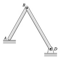
Chapter 10, Problem 10.20P
Locate the instant center of rotation of bar AB for each case shown.
Expert Solution & Answer
Want to see the full answer?
Check out a sample textbook solution
Students have asked these similar questions
Please do not use any AI tools to solve this question.
I need a fully manual, step-by-step solution with clear explanations, as if it were done by a human tutor.
No AI-generated responses, please.
Please do not use any AI tools to solve this question.
I need a fully manual, step-by-step solution with clear explanations, as if it were done by a human tutor.
No AI-generated responses, please.
[Q2]: The cost information supplied by the cost accountant is as follows:Sales 20,00 units, $ 10 per unitCalculate the (a/ newsale guantity and (b) new selling price to earn the sameVariable cost $ 6 per unit, Fixed Cost $ 30,000, Profit $ 50,000profit ifi) Variable cost increases by $ 2 per unitil) Fixed cost increase by $ 10,000Ili) Variable cost increase by $ 1 per unit and fixed cost reduces by $ 10,000
Chapter 10 Solutions
International Edition---engineering Mechanics: Statics 4th Edition
Ch. 10 - Determine the number of DOF for each of the...Ch. 10 - The uniform bar of weight W is held in equilibrium...Ch. 10 - Bars AB and AC of the mechanism are homogenous...Ch. 10 - The weight of each homogeneous bar of the linkage...Ch. 10 - The 1800-kg boat is suspended from two parallel...Ch. 10 - The 2.4-kg lamp, with center of gravity located at...Ch. 10 - The linkage is made of two homogenous bars of...Ch. 10 - For the frame shown, find the horizontal component...Ch. 10 - The four-bar linkage supports the homogeneous box...Ch. 10 - Prob. 10.10P
Ch. 10 - Determine the ratio P/Q of the forces that are...Ch. 10 - Find the vertical force P that will hold the...Ch. 10 - The linkage of the braking system consists of the...Ch. 10 - The automatic drilling robot must sustain a thrust...Ch. 10 - Determine the couple C for which the mechanism...Ch. 10 - The scissors jack is used to elevate the weight W....Ch. 10 - Prob. 10.17PCh. 10 - Calculate the torque C0 that must be applied to...Ch. 10 - Determine the force F and the angle a required to...Ch. 10 - Locate the instant center of rotation of bar AB...Ch. 10 - Prob. 10.21PCh. 10 - Determine the force P that will keep the mechanism...Ch. 10 - Prob. 10.23PCh. 10 - Prob. 10.24PCh. 10 - Prob. 10.25PCh. 10 - Determine the ratio P/Q for which the linkage will...Ch. 10 - Prob. 10.27PCh. 10 - Prob. 10.28PCh. 10 - If the input force to the compound lever is P = 30...Ch. 10 - Determine the roller reaction at F due to the...Ch. 10 - Prob. 10.31PCh. 10 - Prob. 10.32PCh. 10 - Prob. 10.33PCh. 10 - Prob. 10.34PCh. 10 - Prob. 10.35PCh. 10 - For the pliers shown, determine the relationship...Ch. 10 - When activated by the force P, the gripper cm a...Ch. 10 - Prob. 10.38PCh. 10 - The hinge is of the type used on some automobiles,...Ch. 10 - The spring attached to the sliding collar is...Ch. 10 - The weight W is suspended from end B of the...Ch. 10 - The uniform bar of weight W and length L = 1.8R...Ch. 10 - A slender homogeneous bar is bent into a right...Ch. 10 - The body shown is a composite of a hemisphere and...Ch. 10 - Prob. 10.45PCh. 10 - The uniform bar AB of weight W and length L is...Ch. 10 - Uniform rods of weights W1 and W2 are welded to...Ch. 10 - Prob. 10.48PCh. 10 - The semi-cylinder of radius r is placed on a...Ch. 10 - Prob. 10.50PCh. 10 - The spring attached to the homogenous bar of...Ch. 10 - The spring is connected to a rope that passes over...Ch. 10 - Find the equilibrium positions of the 30-lb...Ch. 10 - The mechanism of negligible weight supports the...Ch. 10 - Solve Prob. 10.54 assuming that A and B are...Ch. 10 - The stiffness of the ideal spring that is...Ch. 10 - Find the stable equilibrium position of the system...Ch. 10 - The uniform bar AB of weight W = kL is in...Ch. 10 - The weight of the uniform bar AB is W. The...Ch. 10 - The weightless bars AB and CE, together with the...Ch. 10 - Prob. 10.61PCh. 10 - The bar ABC is supported by three identical, ideal...
Knowledge Booster


Learn more about
Need a deep-dive on the concept behind this application? Look no further. Learn more about this topic, mechanical-engineering and related others by exploring similar questions and additional content below.Similar questions
- can you please help me perform Visual Inspection and Fractography of the attatched image: Preliminary examination to identify the fracture origin, suspected fatigue striation, and corrosion evidences.arrow_forwardcan you please help[ me conduct Causal Analysis (FTA) on the scenario attatched: FTA diagram which is a fault tree analysis diagram will be used to gain an overview of the entire path of failure from root cause to the top event (i.e., the swing’s detachment) and to identify interactions between misuse, material decay and inspection errors.arrow_forwardhi can you please help me in finding the stress intensity factor using a k-calcluator for the scenario attathced in the images.arrow_forward
- Hi, can you please help me .Identify and justify suitable analytical techniques of the scenario below, bearing in mind the kinds of information being handled to reach a conclusion (methodology). A child swing set was discovered to have failed at the fixing at the top of the chains connecting the seat to the top of the swing set. A 12 mm threaded steel bolt, connecting the shackle to the top beam, failed at the start of the threaded region on the linkage closest to the outside side of the swing set . The linkage and bolts were made of electro galvanised mild steel . The rigid bar chain alternatives and fixings were of the same material and appeared to be fitted in accordance with guidelines. The yield strength of the steel used is 260 MPa and the UTS is 380 MPa. The bolt that failed was threaded using a standard thread with a pitch (distance between threads) of 1.75 mm and a depth of approximately 1.1 mm. The swing set in question had been assigned to ‘toddlers’ with the application of…arrow_forwardHi, can you please define and calculate the failure mode of the linkage that failed on the swing (images added) : A child swing set was discovered to have failed at the fixing at the top of the chains connecting the seat to the top of the swing set. A 12 mm threaded steel bolt, connecting the shackle to the top beam, failed at the start of the threaded region on the linkage closest to the outside side of the swing set . The linkage and bolts were made of electro galvanised mild steel . The rigid bar chain alternatives and fixings were of the same material and appeared to be fitted in accordance with guidelines. The yield strength of the steel used is 260 MPa and the UTS is 380 MPa. The bolt that failed was threaded using a standard thread with a pitch (distance between threads) of 1.75 mm and a depth of approximately 1.1 mm. The swing set in question had been assigned to ‘toddlers’ with the application of a caged-type seat. However, the location was within the play area not…arrow_forwardPage 11-68. The rectangular plate shown is subjected to a uniaxial stress of 2000 psi. Compute the shear stress and the tensile developed on a plane forming an angle of 30° with the longitud axis of the member. (Hint: Assume a cross-sectional area of unity) 2000 psi 2000 psi hparrow_forward
- 11-70. A shear stress (pure shear) of 5000 psi exists on an element. (a) Determine the maximum tensile and compressive stresses caused in the element due to this shear. (b) Sketch the element showing the planes on which the maximum tensile and compressive stresses act.arrow_forward11-20. An aluminum specimen of circular cross section, 0.50 in. in diameter, ruptured under a tensile load of 12,000 lb. The plane of failure was found to be at 48° with a plane perpendicular to the longitudinal axis of the specimen. (a) Compute the shear stress on the failure plane. (b) Compute the maximum tensile stress. (c) Compute the tensile stress on the failure plane. hparrow_forwardA long flat steel bar 13 mm thick and 120 mm wide has semicircular grooves as shown and carries a tensile load of 50 kN Determine the maximum stress if plate r= 8mm r=21mm r=38mmarrow_forward
- Problem 13: F₁ = A =250 N 30% Determine the moment of each of the three forces about point B. F₂ = 300 N 60° 2 m -3 m B 4 m F3=500 Narrow_forward3 kN 3 kN 1.8 kN/m 80 mm B 300 mm D an 1.5 m-1.5 m--1.5 m- PROBLEM 5.47 Using the method of Sec. 5.2, solve Prob. 5.16 PROBLEM 5.16 For the beam and loading shown, determine the maximum normal stress due to bending on a transverse section at C.arrow_forward300 mm 3 kN 3 kN 450 N-m D E 200 mm 300 mm PROBLEM 5.12 Draw the shear and bending-moment diagrams for the beam and loading shown, and determine the maximum absolute value (a) of the shear, (b) of the bending moment.arrow_forward
arrow_back_ios
SEE MORE QUESTIONS
arrow_forward_ios
Recommended textbooks for you
 International Edition---engineering Mechanics: St...Mechanical EngineeringISBN:9781305501607Author:Andrew Pytel And Jaan KiusalaasPublisher:CENGAGE L
International Edition---engineering Mechanics: St...
Mechanical Engineering
ISBN:9781305501607
Author:Andrew Pytel And Jaan Kiusalaas
Publisher:CENGAGE L
Force | Free Body Diagrams | Physics | Don't Memorise; Author: Don't Memorise;https://www.youtube.com/watch?v=4Bwwq1munB0;License: Standard YouTube License, CC-BY