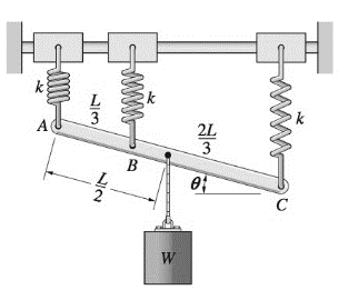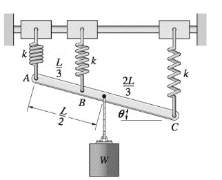
The bar ABC is supported by three identical, ideal springs. Note that the springs are always vertical because the collars to which they are attached are free to slide on the horizontal rail. Find the angle

The angle
Answer to Problem 10.62P
The value ofangle at the stable equilibrium positions is
Explanation of Solution
Given Information:
The weight of the load = W
The stiffness of each spring = k
Given that
The following figure is given,

Calculation:
Consider the following figure,

To calculate the angle for the equilibrium position, let us calculate the potential energy of the system. The total potential energy of the system consists of potential energy of the weight (Vg) and the potential energy of the springs (Ve)
The total potential energy =
Putting the value of Yg and s in equation (1)
The potential energy of the system comes out to be
Now, let us take the first derivative of the total potential energy of the system,
Now, the principle of minimum potential energy can be used to find the value of angle
The roots of equation
Now, differentiating equation 3 again to get
Thus, system is at unstable equilibrium at
Thus, system is at stable equilibrium at
Conclusion:
Therefore, the value ofangle at the stable equilibrium positions is
Want to see more full solutions like this?
Chapter 10 Solutions
International Edition---engineering Mechanics: Statics 4th Edition
- Problem 1: Analyze the canard-wing combination shown in Fig. 1. The canard and wing are made of the same airfoil section and have AR AR, S = 0.25, and = 0.45% 1. Develop an expression for the moment coefficient about the center of gravity in terms of the shown parameters (, and zg) and the three-dimensional aerodynamic characteristics of the used wing/canard (CL C and CM). 2. What is the range of the cg location for this configuration to be statically stable? You may simplify the problem by neglecting the upwash (downwash) effects between the lifting surfaces and the drag contribution to the moment. You may also assume small angle approximation. Figure 1: Canard-Wing Configuration.arrow_forwardProblem 2: Consider the Boeing 747 jet transport, whose layout is shown in Fig. 2 and has the following characteristics: xoa 0.25, 8 5500/2, b 195.68ft, 27.31ft, AR, 3.57, V = 0.887 Determine the wing and tail contributions to the CM-a curve. You may want to assume CM, reasonable assumptions (e.g., -0.09, 0, -4°. i=0.0°, and i = -2.0°. Make any other 0.9).arrow_forwardZ Fy = 100 N Fx = 100 N F₂ = 500 N a = 500 mm b = 1000 mm Figure 2: Schematics for problem 3. 1. Draw the moment (M), axial (N), and shear (S) diagrams. Please note that this is a 3D problem and you will have moment (M) and shear (S) along two different axes. That means that you will have a total of 5 diagrams.arrow_forward
- An ideal gas with MW of 29 g/mol, cp = 1.044 kJ/kgK and c₁ = 0.745 kJ/kgK contained in a cylinder-piston assembly initially has a pressure of 175 kPa, a temperature of 22°C, and a volume of 0.30 m³. It is heated slowly at constant volume (process 1-2) until the pressure is doubled. It is then expanded slowly at constant pressure (process 2-3) until the volume is doubled. Draw a figure of the system and the PV diagram showing each state and the path each process takes. Determine the total work done by the system and total heat added (J) in the combined process.arrow_forwardplease explain each method used, thank youarrow_forwardDetermine the resultant loadings acting on the cross sections at points D and E of the frame.arrow_forward
- please read everything properly... Take 3 4 5 hrs but solve full accurate drawing on bond paper don't use chat gpt etc okk.... Not old solutions just new solvearrow_forwardplease box out or highlight all the answersarrow_forwardWhat are some ways Historical Data can be used and applied to an estimate?arrow_forward
 International Edition---engineering Mechanics: St...Mechanical EngineeringISBN:9781305501607Author:Andrew Pytel And Jaan KiusalaasPublisher:CENGAGE L
