(a)
The values of gain
Case 1. For
Case 2. For
Case 3. For a root separation factor of 5.
Answer to Problem 10.31P
The values of gains for the PI controller are as follows:
Case 1. For
Case 2. For
Case 3. For a root separation factor of 5,
Explanation of Solution
Given:
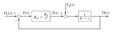
The proportional integral controller of first order plant is as shown below:

Where, the parameter values are as given:
Also, the performance specifications require the time constant of the system to be
Concept Used:
- The transfer functions for the block diagram are as shown below:
- For a second order system, if the root separation factor is K then, we have following conclusions for the roots and their corresponding time constant, that is For roots
For a second order system having a characteristic equation of the form
Also, the corresponding time constant for the system would be
The corresponding time constants of the system would be:
Calculation:
From the block diagram as shown, the transfer functions are as:
Therefore, the characteristic equation for the system is:
On putting the values of parameters in this expression of characteristic equation:
On comparing this equation with form
Undamped natural frequency:
Damping ratio:
Thus, the time constant for the system is:
As the performance specifications require the time constant of the system to be
Therefore, at
Case 1. When
Since,
Case 2. When
Since,
Case 3. When the root separation factor is 5.
For this value of the root separation factor
As given in the question system, performance requires time constant to be 2seconds or say the dominant time constant to be 2 seconds then the secondary time constant would be 0.4 seconds. Therefore, the characteristic roots corresponding to these time constants would be:
Thus, the corresponding characteristic equation for the system will be:
On comparing this equation with
And
Conclusion:
The values of gains for the PI controller areas follows:
Case 1. For
Case 2. For
Case 3. For a root separation factor of 5,
(b)
To plot:
The response
Also, compare the responses obtained in all these cases.
Answer to Problem 10.31P
The response
Explanation of Solution
Given:
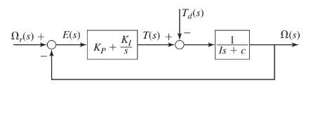
The proportional integral controller of first order plant is as shown below:

Where, the parameter values are as given:
Also, the performance specifications require the time constant of the system to be
The values of gains for the PI controller are as follows:
Case 1. For
Case 2. For
Case 3. For a root separation factor of 5,
Concept Used:
- The transfer functions for the block diagram are as shown below:
Calculation:
From the block diagram as shown, the transfer functions are as:
Therefore, the response
On putting the values of parameters in this expression of characteristic equation:
Case 1. When
Since,
Therefore, for unit-step command response
On simplifying this response of
On taking inverse Laplace transform of this, we have
Case 2. When
Since,
Therefore, for unit-step command response
On simplifying this response of
On taking inverse Laplace transform of this, we have
Case 3. When the root separation factor is 5.
That is, the gain values are
Since,
Therefore, for unit-step command response
On simplifying this response of
On taking inverse Laplace transform of this, we have
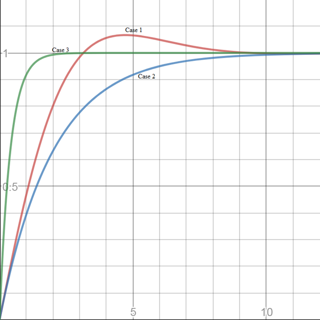
On plotting the responses

Here, on comparing the responses for all the three cases, it is concluded that the response shifts from being underdamped to overdamped for the first two cases. Whereas, for the third case the response remains overdamped in nature however, its settling time is very less comparing the other two cases.
Conclusion:
At the damping ratio
Want to see more full solutions like this?
Chapter 10 Solutions
System Dynamics
- please find Ix and Iy in mm4arrow_forwardHomework#7arrow_forwardComputing Angles of Rotation and Angles of Tilt In each of the following problems, the axis of a hole is shown in a rectangular solid. In order to position the hole axis for drilling, the angle of rotation and the angle of tilt must be determined. Compute angles to the nearer minute in triangles with customary unit sides. Compute angles to the nearer hundredth degree in triangles with metric unit sides. a. Compute the angle of rotation, R. b. Compute the angle of tilt, T. 7. Given: H= 2.600 in. L = 2.400 in. a. W= 1.900 in. 8. Given: H= 55.00 mm b. Use this figure for #7 and #8. AXIS OF HOLE L 48.00 mm W= 30.00 mm H a. b. 9. Given: H = 4.750 in. L = 4.000 in. W= 3.750 in. a. 10. Given: H=42.00 mm b. L37.00 mm W = 32.00 mm a. b. 11. Given: H = 0.970 in. L = 0.860 in. W= 0.750 in. a. 12. Given: H= 22.00 mm L 18.00 mm = W = 15.00 mm a. b. Use this figure for #9 and #10. ZR AXIS OF HOLE Use this figure for #11 and #12. H b. L AXIS OF HOLE Tarrow_forward
- This is a tilt and rotation question. Here are notes attached for reference. I prefer handwritten solutions. ONLY UPLOAD A SOLUTION IF YOU ARE SURE ABOUT THE ANSWER PLEASE. I prefer handwritten solutions.arrow_forwardConsider a constant area semi-infinite fin of a circular cross section of radius r. and thermal conductivity k. The base is maintained at T. and the surface of the fin exchanges heat by convection to an ambient fluid at T with a heat transfer coefficient h. It is desired to increase the heat transfer from the fin. The following suggestions are made: (i) doubling k, (ii) doubling ro, (iii) doubling h. Which suggestion will bring about the largest increase in heat transfer? To x h, T C A h, Tarrow_forwardA 20 cm long 304 stainless steel bar is initially at 18°C. One end of the bar is suddenly maintained at 100°C. Assuming that your finger can tolerate a 60°C temperature, what is the longest time you are willing to wait before you touch the other end? Be on the safe side and select a conservative model. h,T oil bath glass ballarrow_forward
 Elements Of ElectromagneticsMechanical EngineeringISBN:9780190698614Author:Sadiku, Matthew N. O.Publisher:Oxford University Press
 Mechanics of Materials (10th Edition)Mechanical EngineeringISBN:9780134319650Author:Russell C. HibbelerPublisher:PEARSON
 Thermodynamics: An Engineering ApproachMechanical EngineeringISBN:9781259822674Author:Yunus A. Cengel Dr., Michael A. BolesPublisher:McGraw-Hill Education
 Control Systems EngineeringMechanical EngineeringISBN:9781118170519Author:Norman S. NisePublisher:WILEY
 Mechanics of Materials (MindTap Course List)Mechanical EngineeringISBN:9781337093347Author:Barry J. Goodno, James M. GerePublisher:Cengage Learning
 Engineering Mechanics: StaticsMechanical EngineeringISBN:9781118807330Author:James L. Meriam, L. G. Kraige, J. N. BoltonPublisher:WILEY


