
Videos
The steady-state error due to a unit-ramp command and due to a unit-ramp disturbance of the PI controller used in first order plant for the given cases.
Answer to Problem 10.24P
The peak torque values for all the cases are:
Case 1. For
Error due to unit-ramp command:
Error due to unit-ramp disturbance:
Case 2. For
Error due to unit-ramp command:
Error due to unit-ramp disturbance:
Case 3. For a root separation factor of 10,
Error due to unit-ramp command:
Error due to unit-ramp disturbance:
Explanation of Solution
Given:
The proportional integral controller of first order plant is as shown below:
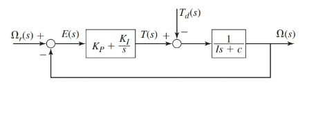
Where, the parameter values are as given:
Also, the performance specifications require the time constant of the system to be
The values of gains for the PI controller are as follows:
Case 1. For
Case 2. For
Case 3. For a root separation factor of 10,
Concept Used:
- The transfer functions for the block diagram are as shown below:
- The steady-state error of a system using final value theorem is:
Calculation:
From the block diagram as shown, the transfer functions are as:
Therefore, the response
And from the block diagram shown in figure, we have
On keeping the values of the parameters such that
Case 1. When
Since,
Therefore, for unit-ramp command response
Thus, the steady-state error for this design is:
Therefore, for zero command response
Thus, the steady-state error for this design is:
Case 2. When
Since,
Therefore, for unit-ramp command response
Thus, the steady-state error for this design is:
Therefore, for zero command response
Thus, the steady-state error for this design is:
Case 3. For a root separation factor of 10,
Since,
Therefore, for unit-ramp command response
Thus, the steady-state error for this design is:
Therefore, for zero command response
Thus, the steady-state error for this design is:
Conclusion:
The peak torque values for all the cases are:
Case 1. For
Error due to unit-ramp command:
Error due to unit-ramp disturbance:
Case 2. For
Error due to unit-ramp command:
Error due to unit-ramp disturbance:
Case 3. For a root separation factor of 10,
Error due to unit-ramp command:
Error due to unit-ramp disturbance:
Want to see more full solutions like this?
Chapter 10 Solutions
System Dynamics


- One end of a thin uniform rod of mass m and length 31 rests against a smooth vertical wall. The other end of the rod is attached by a string of length I to a fixed point which is located a distance 21 from the wall. A horizontal force of magnitude F, is applied to the lower end of the rod as shown. Assuming the rod and the string remain in the same vertical plane perpendicular to the wall, find the angle 9 between the rod and the wall at the position of static equilibrium. Notes: This quiz is going to walk you through a sequence of steps to do this. It won't give you the answers, but it will hopefully get you to see how to approach problems like this so that you have a working reference/template in the future. This is actually a modified version of a problem from the textbook (6.3). Note that in that problem, is not actually given. It has been introduced for convenience as we move through solving the problem, and should not show up in the final answer. DO NOT DO PROBLEM 6.3. It is not…arrow_forwardThis is a tilt and rotation question. Here are notes attached for reference. I prefer handwritten solutions. ONLY UPLOAD A SOLUTION IF YOU ARE SURE ABOUT THE ANSWER PLEASE. I prefer handwritten solutions.(If you had once answered this question don't answer it as I am looking for a different solution)arrow_forwardProblem: You and your team are tasked with designing an around-coil system for an air-conditioning unit that will be installed in a hospital. The system must provide a controlled environment for the hospital's air-conditioning needs, ensuring that fresh air is brought in while exhaust air is expelled, without allowing contamination between the two airflow directions. The air-conditioning system will include two coils and two pumps (one duty pump and one standby pump) in a configuration that accommodates both exhaust and supply airflows. The system needs to comply with ASHRAE Standards, and ASME BPVC Section VIII, with attention to safety, reliability, and efficiency. The system will be used in a climate with moderate temperature variations, and its design will need to consider a range of operating and design specifications. Given data Desired Pressure in the Pipe: According to the (ASHRAE) standard for pressure drop limits. Pipe Diameter: Must comply with standard pipe diameter…arrow_forward
- Assis+ 2019-2018 Assi A. SALE تمارين السيطرة النوعية 1- سحبت عينة عشوائية يومياً تتكون من 50 دائرة كهربائية تستخدم لـ صناعة إحدى الأجهزة الأليكترونية ولمدة 20 يوماً ، وبعد فحصها كانت عدد الدوائر المعابة لكل يوم كالآتي : 43.2.6.3.1.3.2.9.3.5.3.2.5.2.2.1.3.2.1 أوجد حدي السيطرة النوعية لنسبة الوحدات المعابة (ans.0, 0.1533) 2- سحبت 10 عينات عشوائية من مصنع لتعبئة الأسماك البحرية وكل عينة تحتوي على كانت أوزانها ( باوند ( كالآتي : ب ، 1 71 X₁ X₂ 1.04 1.01 measurements X3 X4 X5 0.98 1.02 1.00 2 1.02 0.97 0.96 1.01 1.02 3 1.01 1.07 4 0.98 0.97 1.02 0.99 1.03 1.00 0.98 0,98 5 6 0.99 1.03 1.02 0.95 0.98 1.02 1.01 1.04 1.02 0.95 7 1.00 0.99 0.99 1.02 1.03 1.04 0.99 1.02 0.94 8 9 10 1.02 0.98 1.00 0.99 1.02 1.01 1.02 1.01 1.00 1.04 1.09 أوجد حدي السيطرة النوعية : أ) للوسط الحسابي و ب) للمدى (ans. a) 0.9679, 1.0429, b) 0, 0.137) 18 محاضرة السيطرة النوعية / الهندسة الصناعية - 4 ميكانيك / هندسة ج تكريت 3- كون مخطط سيطرة نوعية مناسب للعملية الإنتاجية المتمثلة بالبيانات التالية التي جمعت خلال شهر معين…arrow_forward42 VOLTE 4G+ EV Suggested Que... Problem: You and your team are tasked with designing an around-coil system for an air- conditioning unit that will be installed in a hospital. The system must provide a controlled environment for the hospital's air-conditioning needs, ensuring that fresh air is brought in while exhaust air is expelled, without allowing contamination between the two airflow directions. The air-conditioning system will include two coils and two pumps (one duty pump and one standby pump) in a configuration that accommodates both exhaust and supply airflows. The system needs to comply with ASHRAE Standards, and ASME BPVC Section VIII, with attention to safety, reliability, and efficiency. The system will be used in a climate with moderate temperature variations, and its design will need to consider a range of operating and design specifications. Given data Desired Pressure in the Pipe: According to the (ASHRAE) standard for pressure drop limits. Pipe Diameter: Must comply…arrow_forwardcompute the work done by a fuel-water interaction assuming that the 40,000 kg of mixed oxide fuel and 4000 kg of water expand independently and isentropically to 1 atmosphere. Assume that the initial fuel and water conditions are such that equilibrium mixture temperature achieved is 1945 K. Other water conditions are as follows: Tinitial = 400K, ro initial = 945 kg/m^3, cv = 4184 J/kg-K. Caution: Equation 6.9 is inappropriate for these conditions since the cooland at state e is supercritial.arrow_forward
- If the W12x50 beam below is made of steel having an allowable bending stress of 36 ksi and an allowable shear stress of 15 ksi, determine the maximum cable force, P, that can safely be supported by the beam.arrow_forwardThis is a tilt and rotation question. Here are notes attached for reference. I prefer handwritten solutions. ONLY UPLOAD A SOLUTION IF YOU ARE SURE ABOUT THE ANSWER PLEASE. I prefer handwritten solutions.(If you had once answered this question don't answer it as I am looking for a different solution)arrow_forward3- Find the optimum of y = 9x - 0.1x ^ 2 in the interval 0 <= x <= 100 and alpha = 0.05 Use two and three experiments sequential search methods?arrow_forward
- 1- A manufacturing company is optimizing the cooling time of a newly developed plastic molding process. The goal is to minimize the total production cost, which depends on the cooling time (t) in minutes. The production cost (C, in dollars) is given by: C=50+10(t)-0.5(t)^2 where: 5 st≤ 20 (cooling time in minutes) Using the Two-Experiments Sequential Method (up to five cycles) find the optimal cooling time (t) that minimizes the production cost. 3:29 مarrow_forward2- Find the optimum minimum point of y = x²-6x + 2 in the interval 0 ≤ x ≤ 10 using sequential search method with three experiments. the accuracy a = 0.06. 3- Find the optimum of y = 9x -0.1 x² in the interval 0 ≤ x ≤ 100, and α = 0.05 Use two and three experiments sequential search methods?arrow_forwardhand-written solutions only pleasearrow_forward
 Elements Of ElectromagneticsMechanical EngineeringISBN:9780190698614Author:Sadiku, Matthew N. O.Publisher:Oxford University Press
 Mechanics of Materials (10th Edition)Mechanical EngineeringISBN:9780134319650Author:Russell C. HibbelerPublisher:PEARSON
 Thermodynamics: An Engineering ApproachMechanical EngineeringISBN:9781259822674Author:Yunus A. Cengel Dr., Michael A. BolesPublisher:McGraw-Hill Education
 Control Systems EngineeringMechanical EngineeringISBN:9781118170519Author:Norman S. NisePublisher:WILEY
 Mechanics of Materials (MindTap Course List)Mechanical EngineeringISBN:9781337093347Author:Barry J. Goodno, James M. GerePublisher:Cengage Learning
 Engineering Mechanics: StaticsMechanical EngineeringISBN:9781118807330Author:James L. Meriam, L. G. Kraige, J. N. BoltonPublisher:WILEY