
Concept explainers
Videos
(a) Determine s on the transmission line of Figure 10.32. Note that the dielectric is air. (b) Find the input impedance. (c) If
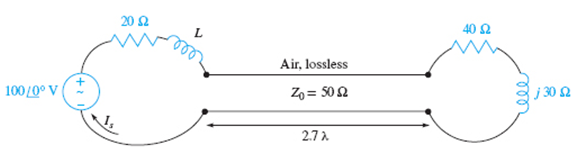
Figure 10.32 See Problem 10.20.
(a)
The value ofs on the transmission line.
Answer to Problem 10.20P
The value of son the transmission line is 2.
Explanation of Solution
Given:
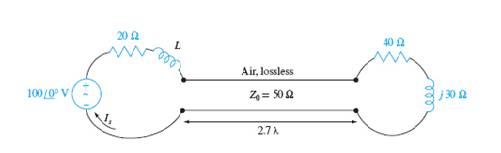
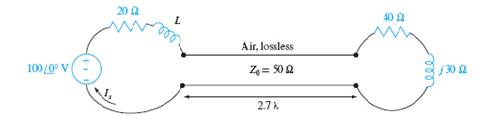
The given figure is shown below.

Concept Used:
The term s is calculated by
Calculation:
The reflection coefficient is
The magnitude of the reflection coefficient is,
The standing wave ratio is calculated as
Conclusion:
The value of s in the transmission line is 2.
(b)
The input impedance.
Answer to Problem 10.20P
The input impedance of the transmission line is
Explanation of Solution
Given:
The given figure is shown below.
Concept Used:
The input impedance is calculated by
Calculation:
The input impedance of the transmission line is calculated as
Let
Conclusion:
The input impedance of the transmission line is
(c)
The source current
Answer to Problem 10.20P
The source current is
Explanation of Solution
Given:

Calculation:
The source current is calculated by
Let
Conclusion:
Thus, the source current is
(d)
The value of L which produces maximum value for
Answer to Problem 10.20P
The value of L which produces maximum value for
Explanation of Solution
Given:
The given circuit is shown below.
Concept Used:
The maximum value of L is calculated by
Calculation:
The magnitude of the source current is,
Differentiating with respect to L,
Conclusion:
The value of L which produces maximum value for
(e)
The average power delivered by the source.
Answer to Problem 10.20P
The average power delivered by the source is,
Explanation of Solution
Given:
The given circuit is shown below.

Concept Used:
The average power is calculated by
Calculation:
Considering the real part only
Average power is calculated as
Conclusion:
Thus, the average power delivered by the source is,
(f)
Average power delivered to ZL.
Answer to Problem 10.20P
The average power delivered to the load is
Explanation of Solution
Given:

Concept Used:
The average power delivered is calculated by
Calculation:
Thus, the total power delivered to the load is
Conclusion:
Thus, the average power delivered to the load is
Want to see more full solutions like this?
Chapter 10 Solutions
Engineering Electromagnetics


- Determine i(t) for t≥ 0 given that the circuit below had been in steady state for a long time prior to t = 0. Also, I₁ = 1 5 A, R₁ =22, R2 =10 Q2, R3 = 32, R4 =7 2, and L=0.15 H. Also fill the table. m L ww R2 t = 0 R₁ 29 R3 R4 Time 0 iL(t) 0 8arrow_forwardPlease help explain this problemarrow_forward+ P = 16 W w w P = 8 W I R₁ R2 E = RT=322 1- Determine R1, R2, E ΙΩarrow_forward
- + 30 V = - 20 V + R 2- Use KVL to find the voltage V - V + + 8 Varrow_forwardFind the Thévenin equivalent circuit for the portions of the networks in Figure external to the elements between points a and b. a R₁ 2002 I = 0.1 A 0° Xc : 32 Ω R2 = 6802 20 Ω фъarrow_forwardFind the Norton equivalent circuit for the network external to the elements between a and b for the networks in Figure. E1 = 120 V Z 0° R ww 10 Ω Xc XL · 000 802 802 ① I = 0.5 AZ 60° ZL barrow_forward
- Using superposition, determine the current through inductance XL for each network in Figure I = 0.3 A 60° XL 000 802 XC 502 Ω E 10 V0° =arrow_forwardFind the Thévenin equivalent circuit for the portions of the networks in Figure external to the elements between points a and b. E = 20 VZ0° + R ww 2 ΚΩ Хо XL 000 6ΚΩ 3 ΚΩ b RLarrow_forwardWhat percentage of the full-load current of a thermally protected continuous-duty motor of more than one Hp can the trip current be, if the full-load current is 15 amperes? Ο 122 Ο 140 156 O 170arrow_forward
- Q3arrow_forwardIn thinkercad can you make a parallel series circuit with a resistors and a voltage source explain how the voltage and current moves through the circuit, and explaining all the components, and if you were to break the circuit to find the current how would you do that? Please show visuals if possible.arrow_forwardIn thinkercad can you make a series circuit with a resistors and a voltage source explain how the voltage and current moves through the circuit, and explaining all the components, and if you were to break the circuit to find the current how would you do that? Please show visuals if possible.arrow_forward
 Introductory Circuit Analysis (13th Edition)Electrical EngineeringISBN:9780133923605Author:Robert L. BoylestadPublisher:PEARSON
 Delmar's Standard Textbook Of ElectricityElectrical EngineeringISBN:9781337900348Author:Stephen L. HermanPublisher:Cengage Learning
 Programmable Logic ControllersElectrical EngineeringISBN:9780073373843Author:Frank D. PetruzellaPublisher:McGraw-Hill Education
 Fundamentals of Electric CircuitsElectrical EngineeringISBN:9780078028229Author:Charles K Alexander, Matthew SadikuPublisher:McGraw-Hill Education
 Electric Circuits. (11th Edition)Electrical EngineeringISBN:9780134746968Author:James W. Nilsson, Susan RiedelPublisher:PEARSON
 Engineering ElectromagneticsElectrical EngineeringISBN:9780078028151Author:Hayt, William H. (william Hart), Jr, BUCK, John A.Publisher:Mcgraw-hill Education,