
Basic Engineering Circuit Analysis
11th Edition
ISBN: 9781118539293
Author: J. David Irwin, R. Mark Nelms
Publisher: WILEY
expand_more
expand_more
format_list_bulleted
Concept explainers
Videos
Textbook Question
thumb_up100%
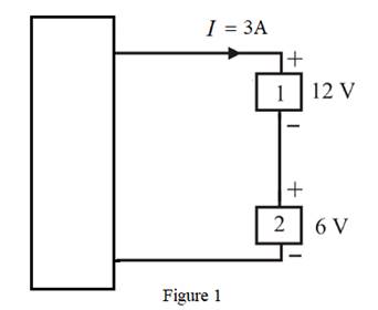
Chapter 1, Problem 27P
(a) In Fig. Pl.27 (a),
(b) In Fig. Pl.27 (b),
Expert Solution & Answer
Want to see the full answer?
Check out a sample textbook solution
Students have asked these similar questions
Assume that a building manager instructed you to install a water heater. The specs on the water heater nameplate reveals the following 240V, 2PH, 60HZ, 5.7KW. The manager insisted for the installation to be done with 10 AWG copper THWN-2 conductor, the length of run is 1200 FT away from the service panel. Calculate the voltage after the installation.
Please confirm that my solution is correct, especially the block diagram. Please DRAW (not type) what the block diagram would look like if it's incorrect.
thank you
use this code on the bottom to answer the question in the photo
clc; clearvars;
% Read the file [y, Fs] = audioread('106miles.wav'); N = length(y); Nfft = 2^nextpow2(N); dt = 1/Fs; t = (0:dt:(N-1)*dt)'; % Ensure t is a column vector y = y - mean(y); % Remove DC component (if not already zero-mean)
% Carrier signal (25 kHz) fc = 25000; % Carrier frequency in Hz carrier = cos(2 * pi * fc * t);
% DSB-SC Modulation modulated_signal = y .* carrier;
% Plot Time Domain Signal figure; subplot(2,1,1); plot(t, y); title('Original Signal (Time Domain)'); xlabel('Time (s)'); ylabel('Amplitude');
subplot(2,1,2); plot(t, modulated_signal); title('DSB-SC Modulated Signal (Time Domain)'); xlabel('Time (s)'); ylabel('Amplitude');
% Frequency Domain (FFT) Y = fft(y, Nfft) / Nfft; Modulated_Y = fft(modulated_signal, Nfft) / Nfft; f = Fs * (0:(Nfft/2)) / Nfft; % Frequency vector
% Plot Frequency Domain Signal figure; subplot(2,1,1); plot(f, abs(Y(1:Nfft/2+1))); title('Original Signal…
Chapter 1 Solutions
Basic Engineering Circuit Analysis
Ch. 1 - If the current in an electric conductor is 2.4 A,...Ch. 1 - Determine the time interval required for a 12�A...Ch. 1 - A lightning bolt carrying 30,000 A lasts for 50...Ch. 1 - If a 12-V battery delivers 100 J in 5 s, find (a)...Ch. 1 - The current in a conductor is 1.5 A. How many...Ch. 1 - If 60 C of charge pass through an electric...Ch. 1 - Determine the number of coulombs of charge...Ch. 1 - Five coulombs of charge pass through the element...Ch. 1 - The current that enters an element is shown in...Ch. 1 - The charge entering the positive terminal of an...
Ch. 1 - The charge entering the positive terminal of an...Ch. 1 - Prob. 12PCh. 1 - The power absorbed by the BOX in Fig. Pl. 13 is...Ch. 1 - The power absorbed by the BOX in Fig. Pl. 14 is...Ch. 1 - The energy absorbed by the BOX in Fig. P1.15 is...Ch. 1 - The charge that enters the BOX in Fig. P1.16 is...Ch. 1 - The energy absorbed by the BOX in Fig. Pl. 17 is...Ch. 1 - The charge entering the upper terminal of the BOX...Ch. 1 - The energy absorbed by the BOX in Fig. Pl. 19 is...Ch. 1 - Determine the amount of power absorbed or supplied...Ch. 1 - Calculate the power absorbed by element A in Fig....Ch. 1 - Calculate the power supplied by element A in Fig....Ch. 1 - Element A in the diagram in Fig. PI .23 absorbs 30...Ch. 1 - Element B in the diagram in Fig. P1.24 supplies 60...Ch. 1 - Element B in the diagram in Fig. PI .25 supplies...Ch. 1 - Element B in the diagram in Fig. Pl.26 supplies 72...Ch. 1 - (a) In Fig. Pl.27 (a), P1=36W. Is element 2...Ch. 1 - Two elements are connected in series, as shown in...Ch. 1 - Element 2 in Fig. Pl.29 absorbed 32W. Find the...Ch. 1 - Choose Is such that the power absorbed by element...Ch. 1 - Find the power that is absorbed or supplied by the...Ch. 1 - Find the power that is absorbed or supplied by the...Ch. 1 - Compute the power that is absorbed or supplied by...Ch. 1 - Find the power that is absorbed or supplied by...Ch. 1 - Find Ix in the network in Fig. P1.35.Ch. 1 - Prob. 36PCh. 1 - Find the power absorbed or supplied by element 1...Ch. 1 - Find the power absorbed or supplied by element 3...Ch. 1 - Find the power absorbed or supplied by element 1...Ch. 1 - Find Vx in the network in Fig. P1.40 using...Ch. 1 - Find Ix in the circuit in Fig. P1.41 using...Ch. 1 - Is the source Vs in the network in Fig. P1.42...Ch. 1 - Find I0 in the network in Fig. P1.43 using...Ch. 1 - Calculate the power absorbed by each element in...Ch. 1 - Calculate the power absorbed by each element in...Ch. 1 - In the circuit in Fig. P1.46, element 1 absorbs 40...
Knowledge Booster


Learn more about
Need a deep-dive on the concept behind this application? Look no further. Learn more about this topic, electrical-engineering and related others by exploring similar questions and additional content below.Similar questions
- 5-9 A 230 V shunt motor has a nominal arma- ture current of 60 A. If the armature resist- ance is 0.152, calculate the following: a. The counter-emf [V] b. The power supplied to the armature [W] c. The mechanical power developed by the motor, [kW] and [hp] 5-10 a. In Problem 5-9 calculate the initial start- ing current if the motor is directly con- nected across the 230 V line. b. Calculate the value of the starting resistor needed to limit the initial current to 115 A.arrow_forwardhow to solve this?arrow_forwardFor the circuit in Fig. P8.52, choose the load impedance ZLso that the power dissipated in it is a maximum. How much powerwill that be?arrow_forward
- how to solve the attached question? please explain or give reference where required in the solution.arrow_forwardHANDWRITTEN SOLUTION REQUIRED NOT USING CHATGPTarrow_forwardPlease only do part E and F. Please show your work and be as detailed as possible. Please explain the relationship between K the gain and stability of the system. Also, show how to plot the poles and why they are on either the real or imaginary axis. What is it about the example that indicated that? thank youarrow_forward
- Please draw the block diagram for this problem and explain how. thank youarrow_forwardPlease show your work and be as detailed as possible. I would like to really understand the connection between the type of loop, the dampness, and the gain, K. Thank youarrow_forwardIn the zone refining of silicon, an RF-heater is used to remove trace amounts of impuritiesfrom the silicon. If the silicon has the impurity of 10^14 Co (k = 8*10^-6) what is the purityof the crystal after one pass of the zone refiner? After two passes? Plot concentration as afunction of crystal length from 0 to 8ft (total length of the crystal). The width of the moltenzone is 5”.arrow_forward
arrow_back_ios
SEE MORE QUESTIONS
arrow_forward_ios
Recommended textbooks for you
 Introductory Circuit Analysis (13th Edition)Electrical EngineeringISBN:9780133923605Author:Robert L. BoylestadPublisher:PEARSON
 Delmar's Standard Textbook Of ElectricityElectrical EngineeringISBN:9781337900348Author:Stephen L. HermanPublisher:Cengage Learning
 Programmable Logic ControllersElectrical EngineeringISBN:9780073373843Author:Frank D. PetruzellaPublisher:McGraw-Hill Education
 Fundamentals of Electric CircuitsElectrical EngineeringISBN:9780078028229Author:Charles K Alexander, Matthew SadikuPublisher:McGraw-Hill Education
 Electric Circuits. (11th Edition)Electrical EngineeringISBN:9780134746968Author:James W. Nilsson, Susan RiedelPublisher:PEARSON
 Engineering ElectromagneticsElectrical EngineeringISBN:9780078028151Author:Hayt, William H. (william Hart), Jr, BUCK, John A.Publisher:Mcgraw-hill Education,
Introductory Circuit Analysis (13th Edition)
Electrical Engineering
ISBN:9780133923605
Author:Robert L. Boylestad
Publisher:PEARSON
Delmar's Standard Textbook Of Electricity
Electrical Engineering
ISBN:9781337900348
Author:Stephen L. Herman
Publisher:Cengage Learning
Programmable Logic Controllers
Electrical Engineering
ISBN:9780073373843
Author:Frank D. Petruzella
Publisher:McGraw-Hill Education
Fundamentals of Electric Circuits
Electrical Engineering
ISBN:9780078028229
Author:Charles K Alexander, Matthew Sadiku
Publisher:McGraw-Hill Education
Electric Circuits. (11th Edition)
Electrical Engineering
ISBN:9780134746968
Author:James W. Nilsson, Susan Riedel
Publisher:PEARSON
Engineering Electromagnetics
Electrical Engineering
ISBN:9780078028151
Author:Hayt, William H. (william Hart), Jr, BUCK, John A.
Publisher:Mcgraw-hill Education,
Kirchhoff's Rules of Electrical Circuits; Author: Flipping Physics;https://www.youtube.com/watch?v=d0O-KUKP4nM;License: Standard YouTube License, CC-BY