
Basic Engineering Circuit Analysis
11th Edition
ISBN: 9781118539293
Author: J. David Irwin, R. Mark Nelms
Publisher: WILEY
expand_more
expand_more
format_list_bulleted
Videos
Textbook Question
thumb_up100%
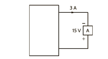
Chapter 1, Problem 21P
Calculate the power absorbed by element A in Fig. PI .21.
Expert Solution & Answer
Want to see the full answer?
Check out a sample textbook solution
Students have asked these similar questions
Q7
Q8
Q18
Chapter 1 Solutions
Basic Engineering Circuit Analysis
Ch. 1 - If the current in an electric conductor is 2.4 A,...Ch. 1 - Determine the time interval required for a 12�A...Ch. 1 - A lightning bolt carrying 30,000 A lasts for 50...Ch. 1 - If a 12-V battery delivers 100 J in 5 s, find (a)...Ch. 1 - The current in a conductor is 1.5 A. How many...Ch. 1 - If 60 C of charge pass through an electric...Ch. 1 - Determine the number of coulombs of charge...Ch. 1 - Five coulombs of charge pass through the element...Ch. 1 - The current that enters an element is shown in...Ch. 1 - The charge entering the positive terminal of an...
Ch. 1 - The charge entering the positive terminal of an...Ch. 1 - Prob. 12PCh. 1 - The power absorbed by the BOX in Fig. Pl. 13 is...Ch. 1 - The power absorbed by the BOX in Fig. Pl. 14 is...Ch. 1 - The energy absorbed by the BOX in Fig. P1.15 is...Ch. 1 - The charge that enters the BOX in Fig. P1.16 is...Ch. 1 - The energy absorbed by the BOX in Fig. Pl. 17 is...Ch. 1 - The charge entering the upper terminal of the BOX...Ch. 1 - The energy absorbed by the BOX in Fig. Pl. 19 is...Ch. 1 - Determine the amount of power absorbed or supplied...Ch. 1 - Calculate the power absorbed by element A in Fig....Ch. 1 - Calculate the power supplied by element A in Fig....Ch. 1 - Element A in the diagram in Fig. PI .23 absorbs 30...Ch. 1 - Element B in the diagram in Fig. P1.24 supplies 60...Ch. 1 - Element B in the diagram in Fig. PI .25 supplies...Ch. 1 - Element B in the diagram in Fig. Pl.26 supplies 72...Ch. 1 - (a) In Fig. Pl.27 (a), P1=36W. Is element 2...Ch. 1 - Two elements are connected in series, as shown in...Ch. 1 - Element 2 in Fig. Pl.29 absorbed 32W. Find the...Ch. 1 - Choose Is such that the power absorbed by element...Ch. 1 - Find the power that is absorbed or supplied by the...Ch. 1 - Find the power that is absorbed or supplied by the...Ch. 1 - Compute the power that is absorbed or supplied by...Ch. 1 - Find the power that is absorbed or supplied by...Ch. 1 - Find Ix in the network in Fig. P1.35.Ch. 1 - Prob. 36PCh. 1 - Find the power absorbed or supplied by element 1...Ch. 1 - Find the power absorbed or supplied by element 3...Ch. 1 - Find the power absorbed or supplied by element 1...Ch. 1 - Find Vx in the network in Fig. P1.40 using...Ch. 1 - Find Ix in the circuit in Fig. P1.41 using...Ch. 1 - Is the source Vs in the network in Fig. P1.42...Ch. 1 - Find I0 in the network in Fig. P1.43 using...Ch. 1 - Calculate the power absorbed by each element in...Ch. 1 - Calculate the power absorbed by each element in...Ch. 1 - In the circuit in Fig. P1.46, element 1 absorbs 40...
Additional Engineering Textbook Solutions
Find more solutions based on key concepts
A syntax error does not prevent a program from being compiled and executed.
Starting Out with Python (4th Edition)
What types of relationships between values can you test with relational operators?
Starting Out with Programming Logic and Design (5th Edition) (What's New in Computer Science)
Create an application that converts Celsius to Fahrenheit. The formula is F = 1.8 C + 32 where F is the Fahren...
Starting Out With Visual Basic (8th Edition)
A 100-mm-long rod has a diameter of 15 mm. If an axial tensile load of 10 kN is applied to it, determine the ch...
Mechanics of Materials (10th Edition)
A pet store sells dogs, cats, birds, and hamsters. Write a declaration for an enumerated data type that can rep...
Starting Out with Java: From Control Structures through Data Structures (4th Edition) (What's New in Computer Science)
3.1 Discuss the differences between an error and a residual.
Elementary Surveying: An Introduction To Geomatics (15th Edition)
Knowledge Booster


Learn more about
Need a deep-dive on the concept behind this application? Look no further. Learn more about this topic, electrical-engineering and related others by exploring similar questions and additional content below.Similar questions
- Prelab Information Laboratory Preliminary Discussion Second-order RLC Circuit Analysis The second-order RLC circuit shown in figure 1 below represents all voltages and impedances as functions of the complex variable, s. Note, of course, that the impedances associated with R, RL, and Rs are constant independent of frequency, so the 's' notation is omitted. Again, one of the advantages of s-domain analysis is that we can apply all of the circuit analysis techniques learned for AC and DC circuits. ZI(s) Zc(s) Rs w RL ww + + VRS(S) VRL(S) VL(s) Vc(s) VR(S) R Vs(s) Figure 1: A second-order RLC circuit represented in the s-domain. To generate the s-domain expression for the output voltage, Vout(s) = VR(S), for the circuit shown in figure 1, we can apply voltage division in the s-domain as shown in equation 1 below. For equation 1 we define the following circuit parameters. RT=RS + RL + R where: R₁ = Total series resistance Rs Signal generator output resistance (fixed) Inductor internal…arrow_forward5.137 The BJT in the circuit of Fig. 5.137 has ẞ = 100. (a) Find the de collector current and the de voltage at the collector. (b) Replacing the transistor by its T model, draw the small-signal equivalent circuit of the amplifier. Analyze the resulting circuit to determine the voltage gain vo/vi. V ww 0.3 mA 300 ΚΩ = 250 Ω Va 30 ΚΩ www|| Fig. 5.137arrow_forwardsolve this, show all steps, no ai pz, please draw it outarrow_forward
- NO AI PLEASE WILL REJECTarrow_forward"?Can the expert help me solve only a bonus question using Arduino" The system must control 3 LEDs (Red, Green, and Blue) to operate in 4 different lighting modes: Mode 3: LEDs fade in and out smoothly (PWM control) in the order Red Green → Blue. Bonus Challenge (Potentiometer Control): The potentiometer (connected to pin A0) allows for dynamic control of the brightness during the fading mode (Mode 3). This allows the user to adjust how bright or dim the LEDs should fade in and out. This solution meets the project requirements, including the current limits, and provides interactive functionality with the push button and potentiometer.arrow_forwardSee the attached image for answeringarrow_forward
arrow_back_ios
SEE MORE QUESTIONS
arrow_forward_ios
Recommended textbooks for you
 Introductory Circuit Analysis (13th Edition)Electrical EngineeringISBN:9780133923605Author:Robert L. BoylestadPublisher:PEARSON
 Delmar's Standard Textbook Of ElectricityElectrical EngineeringISBN:9781337900348Author:Stephen L. HermanPublisher:Cengage Learning
 Programmable Logic ControllersElectrical EngineeringISBN:9780073373843Author:Frank D. PetruzellaPublisher:McGraw-Hill Education
 Fundamentals of Electric CircuitsElectrical EngineeringISBN:9780078028229Author:Charles K Alexander, Matthew SadikuPublisher:McGraw-Hill Education
 Electric Circuits. (11th Edition)Electrical EngineeringISBN:9780134746968Author:James W. Nilsson, Susan RiedelPublisher:PEARSON
 Engineering ElectromagneticsElectrical EngineeringISBN:9780078028151Author:Hayt, William H. (william Hart), Jr, BUCK, John A.Publisher:Mcgraw-hill Education,
Introductory Circuit Analysis (13th Edition)
Electrical Engineering
ISBN:9780133923605
Author:Robert L. Boylestad
Publisher:PEARSON
Delmar's Standard Textbook Of Electricity
Electrical Engineering
ISBN:9781337900348
Author:Stephen L. Herman
Publisher:Cengage Learning
Programmable Logic Controllers
Electrical Engineering
ISBN:9780073373843
Author:Frank D. Petruzella
Publisher:McGraw-Hill Education
Fundamentals of Electric Circuits
Electrical Engineering
ISBN:9780078028229
Author:Charles K Alexander, Matthew Sadiku
Publisher:McGraw-Hill Education
Electric Circuits. (11th Edition)
Electrical Engineering
ISBN:9780134746968
Author:James W. Nilsson, Susan Riedel
Publisher:PEARSON
Engineering Electromagnetics
Electrical Engineering
ISBN:9780078028151
Author:Hayt, William H. (william Hart), Jr, BUCK, John A.
Publisher:Mcgraw-hill Education,
Inductors Explained - The basics how inductors work working principle; Author: The Engineering Mindset;https://www.youtube.com/watch?v=KSylo01n5FY;License: Standard Youtube License