
Basic Engineering Circuit Analysis
11th Edition
ISBN: 9781118539293
Author: J. David Irwin, R. Mark Nelms
Publisher: WILEY
expand_more
expand_more
format_list_bulleted
Concept explainers
Videos
Textbook Question
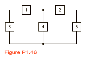
Chapter 1, Problem 46P
In the circuit in Fig.
Expert Solution & Answer

Learn your wayIncludes step-by-step video

schedule02:18
Students have asked these similar questions
you dont need to solve the question i just wanna know the steps and how to find the angle between the voltage difference and the current .
thanks so much
istics of diodes, bipolar junction transistors, and
plain the structure, operation,
1. The purpose of doping in semiconductor diodes is:
a) To control their electrical properties
b) To increase their physical size
c) To enhance their mechanical strength d) To improve their thermal stability
2. In electronics production, your team wants to manufacture a very cheap diode rectifier.
Which of the following rectifier configurations would you select?
a) Half-wave rectifier
c) Full-wave rectifier
b) Bridge rectifier
d) Controlled rectifier
3. The region that a Zener diode operates to provide voltage regulation is:
a) Saturation
c) Reverse bias
b) Breakdown
d) Forward bias
4. In NMOS transistors, the depth of the channel is primarily changed by:
a) VDS
b) lp
c) VGS
d) None of these
5. NMOS transistors have
than PMOS, resulting in better current conduction:
b) Long channel
a) High mobility
c) Low mobility
d) Short channel
6. You are working in electronic production, and your team is asked to…
8.46 The generator circuit shown in Fig. P8.46 (on page 494) isconnected to a distant load via a long coaxial transmission line.The overall circuit can be modeled as in Fig. P8.46(b), in whichthe transmission line is represented by an equivalent impedanceZline = (5+ j2) W.(a) Determine the power factor of voltage source Vs.(b) Specify the capacitance of a shunt capacitor C that wouldraise the power factor of the source to unity when connectedbetween terminals (a,b). The source frequency is 1.5 kHz.
Chapter 1 Solutions
Basic Engineering Circuit Analysis
Ch. 1 - If the current in an electric conductor is 2.4 A,...Ch. 1 - Determine the time interval required for a 12�A...Ch. 1 - A lightning bolt carrying 30,000 A lasts for 50...Ch. 1 - If a 12-V battery delivers 100 J in 5 s, find (a)...Ch. 1 - The current in a conductor is 1.5 A. How many...Ch. 1 - If 60 C of charge pass through an electric...Ch. 1 - Determine the number of coulombs of charge...Ch. 1 - Five coulombs of charge pass through the element...Ch. 1 - The current that enters an element is shown in...Ch. 1 - The charge entering the positive terminal of an...
Ch. 1 - The charge entering the positive terminal of an...Ch. 1 - Prob. 12PCh. 1 - The power absorbed by the BOX in Fig. Pl. 13 is...Ch. 1 - The power absorbed by the BOX in Fig. Pl. 14 is...Ch. 1 - The energy absorbed by the BOX in Fig. P1.15 is...Ch. 1 - The charge that enters the BOX in Fig. P1.16 is...Ch. 1 - The energy absorbed by the BOX in Fig. Pl. 17 is...Ch. 1 - The charge entering the upper terminal of the BOX...Ch. 1 - The energy absorbed by the BOX in Fig. Pl. 19 is...Ch. 1 - Determine the amount of power absorbed or supplied...Ch. 1 - Calculate the power absorbed by element A in Fig....Ch. 1 - Calculate the power supplied by element A in Fig....Ch. 1 - Element A in the diagram in Fig. PI .23 absorbs 30...Ch. 1 - Element B in the diagram in Fig. P1.24 supplies 60...Ch. 1 - Element B in the diagram in Fig. PI .25 supplies...Ch. 1 - Element B in the diagram in Fig. Pl.26 supplies 72...Ch. 1 - (a) In Fig. Pl.27 (a), P1=36W. Is element 2...Ch. 1 - Two elements are connected in series, as shown in...Ch. 1 - Element 2 in Fig. Pl.29 absorbed 32W. Find the...Ch. 1 - Choose Is such that the power absorbed by element...Ch. 1 - Find the power that is absorbed or supplied by the...Ch. 1 - Find the power that is absorbed or supplied by the...Ch. 1 - Compute the power that is absorbed or supplied by...Ch. 1 - Find the power that is absorbed or supplied by...Ch. 1 - Find Ix in the network in Fig. P1.35.Ch. 1 - Prob. 36PCh. 1 - Find the power absorbed or supplied by element 1...Ch. 1 - Find the power absorbed or supplied by element 3...Ch. 1 - Find the power absorbed or supplied by element 1...Ch. 1 - Find Vx in the network in Fig. P1.40 using...Ch. 1 - Find Ix in the circuit in Fig. P1.41 using...Ch. 1 - Is the source Vs in the network in Fig. P1.42...Ch. 1 - Find I0 in the network in Fig. P1.43 using...Ch. 1 - Calculate the power absorbed by each element in...Ch. 1 - Calculate the power absorbed by each element in...Ch. 1 - In the circuit in Fig. P1.46, element 1 absorbs 40...
Additional Engineering Textbook Solutions
Find more solutions based on key concepts
Explain static cursors. Give an example of their use.
Database Concepts (8th Edition)
T F One limitation of the for loop is that only one variable may be initialized in the initialization expressio...
Starting Out with C++ from Control Structures to Objects (9th Edition)
13. Consider the following strange, but true, units:
1 batman = 3 kilograms [kg] 1 hogshead = 63 gallons [gal]
...
Thinking Like an Engineer: An Active Learning Approach (4th Edition)
Show the results on the left segment.
Mechanics of Materials (10th Edition)
In the following exercises, write a program to carry out the task. The program should use variables for each of...
Introduction To Programming Using Visual Basic (11th Edition)
This marks the location of the next item that will be read from a file. a. input position b. delimiter c. point...
Starting Out with Python (4th Edition)
Knowledge Booster


Learn more about
Need a deep-dive on the concept behind this application? Look no further. Learn more about this topic, electrical-engineering and related others by exploring similar questions and additional content below.Similar questions
- 7. MOSFET circuit The MOSFET in the circuit below has V₁ = 1 V and kn = 4 mA/V². a) Is the MOSFET operating in saturation or in the triode region? b) Determine the drain current ID and Vout. + 5 V 5 k Voutarrow_forwardDraw a logic diagram of a 4-bit adder/subtractor then use it to design an Exess-3 to BCD code converter circuit. The circuit has an input (x4 xs x2x) and output (ye ya ya yi)scrarrow_forwardIf waveforms shown in figure below are applied as inputs to a 2-bit comparator (P=P: Po and Q=Q: Q), draw the three output waveforms of the comparator (P>Q, P=Q, Parrow_forwardmicro wavearrow_forwardmicro wavearrow_forwardFor this question, please show how to get the answer using block diagrams. I have included my attempt but I am not close to the answer and I don't understand how to get the T_d(s) expression. Please show the block diagram steps, as in, do not just plug this question into an AI. thank youarrow_forwardOnly expert should attempt this questions, handwritten solution onlyarrow_forwardPlease show formula used and steps as I will study themarrow_forwardQuestion One R C ww (t)T Figure 2: R-C Circuit A series R-C circuit in figure 2, has a step input voltage applied to it. Use Laplace transforms to determine expressions for (a) Current, i(t) flowing in the circuit, given that when t = Os, i=0A [12 marks] (b) Use the expression obtained in (a), calculate the current i(t) flowing in the circuit, when V = 15volts, R = 50, C=1F, t = 1sec [2 marks]arrow_forward7. MOSFET circuit The MOSFET in the circuit below has V₁ = 1 V and kn = 4 mA/V². a) Is the MOSFET operating in saturation or in the triode region? b) Determine the drain current ID and Vout. + 5 V 5 k Voutarrow_forwardNot use ai pleasearrow_forward5. MOSFET circuit The MOSFET in the circuit below has Vt = 0.5 V and kn = 0.4 mA/V2. Determine Vout. + 5 V 1 mA - Vout 6. MOSFET circuit The MOSFET in the circuit below has V₁ = 1 V and kn = 2 mA/V². a) Is the MOSFET operating in saturation or in the triode region? b) Determine the drain current ID. +2V 2 V -2 Varrow_forwardarrow_back_iosSEE MORE QUESTIONSarrow_forward_ios
Recommended textbooks for you
 Introductory Circuit Analysis (13th Edition)Electrical EngineeringISBN:9780133923605Author:Robert L. BoylestadPublisher:PEARSON
 Delmar's Standard Textbook Of ElectricityElectrical EngineeringISBN:9781337900348Author:Stephen L. HermanPublisher:Cengage Learning
 Programmable Logic ControllersElectrical EngineeringISBN:9780073373843Author:Frank D. PetruzellaPublisher:McGraw-Hill Education
 Fundamentals of Electric CircuitsElectrical EngineeringISBN:9780078028229Author:Charles K Alexander, Matthew SadikuPublisher:McGraw-Hill Education
 Electric Circuits. (11th Edition)Electrical EngineeringISBN:9780134746968Author:James W. Nilsson, Susan RiedelPublisher:PEARSON
 Engineering ElectromagneticsElectrical EngineeringISBN:9780078028151Author:Hayt, William H. (william Hart), Jr, BUCK, John A.Publisher:Mcgraw-hill Education,
Introductory Circuit Analysis (13th Edition)
Electrical Engineering
ISBN:9780133923605
Author:Robert L. Boylestad
Publisher:PEARSON
Delmar's Standard Textbook Of Electricity
Electrical Engineering
ISBN:9781337900348
Author:Stephen L. Herman
Publisher:Cengage Learning
Programmable Logic Controllers
Electrical Engineering
ISBN:9780073373843
Author:Frank D. Petruzella
Publisher:McGraw-Hill Education
Fundamentals of Electric Circuits
Electrical Engineering
ISBN:9780078028229
Author:Charles K Alexander, Matthew Sadiku
Publisher:McGraw-Hill Education
Electric Circuits. (11th Edition)
Electrical Engineering
ISBN:9780134746968
Author:James W. Nilsson, Susan Riedel
Publisher:PEARSON
Engineering Electromagnetics
Electrical Engineering
ISBN:9780078028151
Author:Hayt, William H. (william Hart), Jr, BUCK, John A.
Publisher:Mcgraw-hill Education,
Kirchhoff's Rules of Electrical Circuits; Author: Flipping Physics;https://www.youtube.com/watch?v=d0O-KUKP4nM;License: Standard YouTube License, CC-BY