
Basic Engineering Circuit Analysis
11th Edition
ISBN: 9781118539293
Author: J. David Irwin, R. Mark Nelms
Publisher: WILEY
expand_more
expand_more
format_list_bulleted
Videos
Textbook Question
Chapter 1, Problem 17P
The energy absorbed by the BOX in Fig. Pl. 17 is given below. Calculate and sketch the current flowing into the BOX. Also calculate the charge which enters the BOX between 0 and 12 seconds.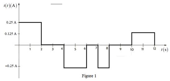
Expert Solution & Answer
Want to see the full answer?
Check out a sample textbook solution
Students have asked these similar questions
Please find Vo using Mesh analysis
Find Vo using mesh analysis
c)
An RC circuit is given in Figure Q1.1, where Vi(t) and Vo(t) are the input and
output voltages.
(i) Derive the transfer function of the circuit.
(ii) With a unit step change of Vi(t) applied to the circuit, derive the time
response of Vo(t) with this step change.
Vi(t)
C₁
Vo(1)
R₂ C2 C3 |
R = 20 ΚΩ = 50 ΚΩ
C=C2=C3=25 μF
Figure Q1.1. RC circuit.
Chapter 1 Solutions
Basic Engineering Circuit Analysis
Ch. 1 - If the current in an electric conductor is 2.4 A,...Ch. 1 - Determine the time interval required for a 12�A...Ch. 1 - A lightning bolt carrying 30,000 A lasts for 50...Ch. 1 - If a 12-V battery delivers 100 J in 5 s, find (a)...Ch. 1 - The current in a conductor is 1.5 A. How many...Ch. 1 - If 60 C of charge pass through an electric...Ch. 1 - Determine the number of coulombs of charge...Ch. 1 - Five coulombs of charge pass through the element...Ch. 1 - The current that enters an element is shown in...Ch. 1 - The charge entering the positive terminal of an...
Ch. 1 - The charge entering the positive terminal of an...Ch. 1 - Prob. 12PCh. 1 - The power absorbed by the BOX in Fig. Pl. 13 is...Ch. 1 - The power absorbed by the BOX in Fig. Pl. 14 is...Ch. 1 - The energy absorbed by the BOX in Fig. P1.15 is...Ch. 1 - The charge that enters the BOX in Fig. P1.16 is...Ch. 1 - The energy absorbed by the BOX in Fig. Pl. 17 is...Ch. 1 - The charge entering the upper terminal of the BOX...Ch. 1 - The energy absorbed by the BOX in Fig. Pl. 19 is...Ch. 1 - Determine the amount of power absorbed or supplied...Ch. 1 - Calculate the power absorbed by element A in Fig....Ch. 1 - Calculate the power supplied by element A in Fig....Ch. 1 - Element A in the diagram in Fig. PI .23 absorbs 30...Ch. 1 - Element B in the diagram in Fig. P1.24 supplies 60...Ch. 1 - Element B in the diagram in Fig. PI .25 supplies...Ch. 1 - Element B in the diagram in Fig. Pl.26 supplies 72...Ch. 1 - (a) In Fig. Pl.27 (a), P1=36W. Is element 2...Ch. 1 - Two elements are connected in series, as shown in...Ch. 1 - Element 2 in Fig. Pl.29 absorbed 32W. Find the...Ch. 1 - Choose Is such that the power absorbed by element...Ch. 1 - Find the power that is absorbed or supplied by the...Ch. 1 - Find the power that is absorbed or supplied by the...Ch. 1 - Compute the power that is absorbed or supplied by...Ch. 1 - Find the power that is absorbed or supplied by...Ch. 1 - Find Ix in the network in Fig. P1.35.Ch. 1 - Prob. 36PCh. 1 - Find the power absorbed or supplied by element 1...Ch. 1 - Find the power absorbed or supplied by element 3...Ch. 1 - Find the power absorbed or supplied by element 1...Ch. 1 - Find Vx in the network in Fig. P1.40 using...Ch. 1 - Find Ix in the circuit in Fig. P1.41 using...Ch. 1 - Is the source Vs in the network in Fig. P1.42...Ch. 1 - Find I0 in the network in Fig. P1.43 using...Ch. 1 - Calculate the power absorbed by each element in...Ch. 1 - Calculate the power absorbed by each element in...Ch. 1 - In the circuit in Fig. P1.46, element 1 absorbs 40...
Additional Engineering Textbook Solutions
Find more solutions based on key concepts
7.13* For a bearing
DE = NUS 5 53’56 ”WT and angles to the right, compute the bearing of PG if angle
DEF 2 88°...
Elementary Surveying: An Introduction To Geomatics (15th Edition)
Create a GUI application that draws the following of a magic wand, using polygons and polylines: Graphics
Java: An Introduction to Problem Solving and Programming (8th Edition)
Days in Current Month Write a program that can determine the number of days in a month for a specified month an...
Starting Out with C++: Early Objects (9th Edition)
What is the role of a compiler?
Problem Solving with C++ (10th Edition)
Determine the horizontal equilibrium force P that must be applied to the handle and the x, y, z components of r...
INTERNATIONAL EDITION---Engineering Mechanics: Statics, 14th edition (SI unit)
In each case, the state of stress x, y, xy produces normal and shear stress components along section AB of the ...
Mechanics of Materials (10th Edition)
Knowledge Booster


Learn more about
Need a deep-dive on the concept behind this application? Look no further. Learn more about this topic, electrical-engineering and related others by exploring similar questions and additional content below.Similar questions
- c) An RC circuit is given in Figure Q1. vi(t) and vo (t) are the input and output voltages. (i) Derive the transfer function of the circuit. (ii) With a unit step change vi(t) applied to the circuit, derive and sketch the time response of the circuit. R₁ R2 v₁(t) R3 C₁ v₁(t) R₁ = R₂ = 10 k R3 = 100 kn C₁ = 100 μF Figure Q1. RC circuit.arrow_forwardc) A RC circuit is given in Figure Q1.1. Vi(t) and Vo(t) are the input and output voltages. (i) Derive the transfer function of the circuit. (ii) With a unit step change of Vi(t) applied to the circuit, derive the time response of the circuit. C₁ C₂ Vi(t) Vo(1) R₁ C₂ R-25 k C=C2=50 µF Figure Q1.1. RC circuit.arrow_forwardAnswer 2 questions for 100 marks Question 1: Process Design [25 marks] An incomplete process design of a flash drum distillation unit is presented in Figure 1. The key variables to be controlled are flow rate, temperature, composition, pressure and liquid level in the drum. Disturbances are observed in the feed temperature and composition. Heat exchangers Drum Vapor Liquid Pump Figure 1: Incomplete process design of a distillation unit Answer the following questions briefly and in a qualitative fashion: a) Determine which sensors and final elements are required so that the important variables can be controlled. Sketch them in the figure using correct instrumentation tags. Describe briefly what instruments you will use and where they should be located. Reflect on the potential presence of a flow controller upstream of your process design (not shown in the diagram). How would this affect the level controller in the drum? b) [10 marks] Describe briefly how you qualitatively determine the…arrow_forward
- Answer 2 questions for 100 marks Question 1: Process Design [25 marks] An incomplete process design of a flash drum distillation unit is presented in Figure 1. The key variables to be controlled are flow rate, temperature, composition, pressure and liquid level in the drum. Disturbances are observed in the feed temperature and composition. Heat exchangers Drum Vapor Liquid Pump Figure 1: Incomplete process design of a distillation unit Answer the following questions briefly and in a qualitative fashion: a) Determine which sensors and final elements are required so that the important variables can be controlled. Sketch them in the figure using correct instrumentation tags. Describe briefly what instruments you will use and where they should be located. Reflect on the potential presence of a flow controller upstream of your process design (not shown in the diagram). How would this affect the level controller in the drum? b) [10 marks] Describe briefly how you qualitatively determine the…arrow_forwardQuestion 2: Process Control [75 marks] As a process engineer, you are tasked to control the process shown in Figure 2. For biomedical engineers, the process could be interpreted as the injection of a solution of a medication compound A, with initial concentration CAO, into a human body, simplified as a Continuously Stirred Tank Reactor (CSTR). Therefore, your task is to analyse and model this process. The equipment consists of a mixing tank, mixing pipe and CSTR. F₁ Сло CA2 V₁ mixing pipe F4 CA4 F3 CA3 mixing tank Fs CAS Vs stirred-tank reactor Figure 2: Mixing and reaction processes Assumptions used for modelling are as follows: I. Both tanks are well mixed and have constant volume and temperature. II. All pipes are short and contribute negligible transportation delay, III. All flow rates are constant. All densities are constant and uniform throughout. IV. The first tank is a mixing tank. V. VI. The mixing pipe has no accumulation, and the concentration CA3 is constant The second tank…arrow_forwarda) Reflect on the assumptions and briefly explain their implications for your model. Do you agree with the assumptions? If not, briefly suggest improved assumptions. [6 marks] b) Derive a linear(ised) model (algebraic or differential equation) relating C'A2(t) to C'Ao(f). How do you define your system? What type of balance do you need to solve for this purpose? [12 marks] c) Derive a linear(ised) model (algebraic or differential equation) relating C'A4(t) to C'A2(f). Show your balance equation. [12 marks] d) Derive a linear(ised) model (algebraic or differential equation) relating C'A5(t) to C'A4(f). Show your balance equation. [12 marks] e) Combine the models in parts (a) to (c) into one equation relating C'A5 to C'Ao using Laplace transforms. [15 marks] f) Is the response (for example to step input) stable or unstable? Is the response periodic? Is the response damped? [6 marks] g) Carry out an inverse Laplace Transform for C'Ao(s) = A CAO/s (step function) to find C'A5(t) in the time…arrow_forward
- I need helparrow_forwardThe values of the circuit elements in the circuit shown in the figure are given below.The initial energies of the capacitors and the coil are zero.Accordingly, how many volts is the voltage vo at t=0.55 seconds? vs(t) = 2cos(4000t)u(t) VR = 19 ohmL = 20 HC1 = 1/5 FC2 = 1/2 Farrow_forwardcould you please show steps on how the answer was derived. Vo(t)=3.922 cos(1000t-71.31')Varrow_forward
- can you show the steps to answer question.arrow_forwardQ2. Figure Q2 shows a block diagram with an input of C(s) and an output R(s). a) C(s) K₁ R(s) K2 1 + 5s 1+2s Figure Q2. Block diagram of control system. Simply the block diagram to get the transfer function of the system C(s)/R(s). b) What is the order of the system? c) What is the gain of the system? d) Determine the values of K₁ and K₂ to obtain a natural frequency w of 0.5 rad/s and damping ratio of 0.4. e) What is the rise time and overshoot of the system with a unit step input?arrow_forwardQ4. a) A purely derivative controller (i.e. with a zero at the origin only) is defined by an improper transfer function. Considering its asymptotic behaviour, explain why a purely derivative controller is difficult to implement in practice. Relate your explanation to the potential limitations on system performance. b) Discuss the potential issues faced by a control system with a large cut-off frequency. Relate your discussion to the implications on system performance. c) The transfer function of a lag compensator is given by 2 KPID(S) = 2.2++0.2s S By using the asymptotic approximation technique: (i) Obtain the standard form and corner frequency for each individual component of KPID(S). (ii) Clearly describe the asymptotic behaviour of each individual component of KPID(S).arrow_forward
arrow_back_ios
SEE MORE QUESTIONS
arrow_forward_ios
Recommended textbooks for you
 Introductory Circuit Analysis (13th Edition)Electrical EngineeringISBN:9780133923605Author:Robert L. BoylestadPublisher:PEARSON
 Delmar's Standard Textbook Of ElectricityElectrical EngineeringISBN:9781337900348Author:Stephen L. HermanPublisher:Cengage Learning
 Programmable Logic ControllersElectrical EngineeringISBN:9780073373843Author:Frank D. PetruzellaPublisher:McGraw-Hill Education
 Fundamentals of Electric CircuitsElectrical EngineeringISBN:9780078028229Author:Charles K Alexander, Matthew SadikuPublisher:McGraw-Hill Education
 Electric Circuits. (11th Edition)Electrical EngineeringISBN:9780134746968Author:James W. Nilsson, Susan RiedelPublisher:PEARSON
 Engineering ElectromagneticsElectrical EngineeringISBN:9780078028151Author:Hayt, William H. (william Hart), Jr, BUCK, John A.Publisher:Mcgraw-hill Education,
Introductory Circuit Analysis (13th Edition)
Electrical Engineering
ISBN:9780133923605
Author:Robert L. Boylestad
Publisher:PEARSON
Delmar's Standard Textbook Of Electricity
Electrical Engineering
ISBN:9781337900348
Author:Stephen L. Herman
Publisher:Cengage Learning
Programmable Logic Controllers
Electrical Engineering
ISBN:9780073373843
Author:Frank D. Petruzella
Publisher:McGraw-Hill Education
Fundamentals of Electric Circuits
Electrical Engineering
ISBN:9780078028229
Author:Charles K Alexander, Matthew Sadiku
Publisher:McGraw-Hill Education
Electric Circuits. (11th Edition)
Electrical Engineering
ISBN:9780134746968
Author:James W. Nilsson, Susan Riedel
Publisher:PEARSON
Engineering Electromagnetics
Electrical Engineering
ISBN:9780078028151
Author:Hayt, William H. (william Hart), Jr, BUCK, John A.
Publisher:Mcgraw-hill Education,
Inductors Explained - The basics how inductors work working principle; Author: The Engineering Mindset;https://www.youtube.com/watch?v=KSylo01n5FY;License: Standard Youtube License