4. Complete the following a. Draw Mohr's circle for the element given and label the axes b. Determine 01, 03, and Tmax for the element c. Determine the stresses (on, Tn) on the plane shown d. Plot the point representing the plane with stresses (On, Tn) on the circle
4. Complete the following a. Draw Mohr's circle for the element given and label the axes b. Determine 01, 03, and Tmax for the element c. Determine the stresses (on, Tn) on the plane shown d. Plot the point representing the plane with stresses (On, Tn) on the circle

ChapterB: Graphical Analysis Of Planar Trusses
Section: Chapter Questions
Problem 10P

Related questions

Question

Transcribed Image Text:### Problem 4: Stress Analysis Using Mohr's Circle
**Objective:**
Complete the following tasks related to stress analysis:
**a. Draw Mohr’s Circle for the given element and label the axes.**
**b. Determine the following for the element:**
- \(\sigma_1\) : Major principal stress
- \(\sigma_3\) : Minor principal stress
- \(\tau_{max}\) : Maximum shear stress
**c. Calculate the stresses \((\sigma_n, \tau_n)\) on the plane shown.**
**d. Plot the point representing the plane with stresses \((\sigma_n, \tau_n)\) on the Mohr's circle.**
### Diagram Description:
- A stress element is shown with dimensions and forces labeled.
- The normal force on the plane \(\sigma_n\) is applied at an angle of 40°.
- Stress values:
- Along the horizontal direction: \(+4, -4\)
- Along the vertical direction: \(8, 5\)
### Graph Information:
- A grid is provided for plotting Mohr’s Circle.
**Steps:**
1. **Mohr’s Circle Construction:**
- Use the stress element to plot the normal and shear stresses on the circle.
- Label the normal stress axis (\(\sigma\)) and the shear stress axis (\(\tau\)).
2. **Principal Stresses & Maximum Shear Stress:**
- Calculate \(\sigma_1\), \(\sigma_3\), and \(\tau_{max}\) using the given stress values.
3. **Stress Determination:**
- Evaluate the plane’s stress components (\(\sigma_n, \tau_n\)) at a 40° angle.
4. **Plotting:**
- Represent (\(\sigma_n, \tau_n\)) on Mohr’s Circle.
**Note for Students:**
Ensure clarity in drawing and labeling the axes on Mohr’s Circle for accurate stress analysis.
Expert Solution
Step 1
Answer
Since we are not allowed to provide handwritten solution we have used Autocad to draw the Mohr's circle based on the given data. Follow the same steps while drawing on graph paper.
major compressive stress = -4
minor compressive stress = -8
shear stress = 4
(a) Take a point A at origin and mark a point B at distance = -4(left) and point C at a distance -8(left) from A.
Now draw perpendicular from B to D and C to E of distance 4.
Join D and E we get centre of Mohr circle O.
Now taking centre O and OE as radius draw the Mohr's circle as shown below.
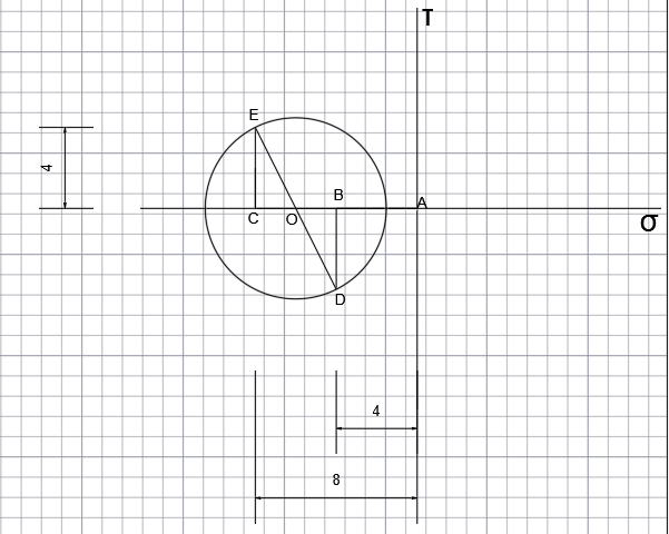
Now draw BD and CE perpedicular equal to 4

Step by step
Solved in 4 steps with 3 images

Knowledge Booster


Learn more about
Need a deep-dive on the concept behind this application? Look no further. Learn more about this topic, civil-engineering and related others by exploring similar questions and additional content below.Recommended textbooks for you

Principles of Foundation Engineering (MindTap Cou…
Civil Engineering
ISBN:
9781305081550
Author:
Braja M. Das
Publisher:
Cengage Learning

Engineering Fundamentals: An Introduction to Engi…
Civil Engineering
ISBN:
9781305084766
Author:
Saeed Moaveni
Publisher:
Cengage Learning
Principles of Foundation Engineering (MindTap Cou…
Civil Engineering
ISBN:
9781305081550
Author:
Braja M. Das
Publisher:
Cengage Learning
Engineering Fundamentals: An Introduction to Engi…
Civil Engineering
ISBN:
9781305084766
Author:
Saeed Moaveni
Publisher:
Cengage Learning

Principles of Foundation Engineering (MindTap Cou…
Civil Engineering
ISBN:
9781337705028
Author:
Braja M. Das, Nagaratnam Sivakugan
Publisher:
Cengage Learning

Principles of Geotechnical Engineering (MindTap C…
Civil Engineering
ISBN:
9781305970939
Author:
Braja M. Das, Khaled Sobhan
Publisher:
Cengage Learning

Fundamentals of Geotechnical Engineering (MindTap…
Civil Engineering
ISBN:
9781305635180
Author:
Braja M. Das, Nagaratnam Sivakugan
Publisher:
Cengage Learning