
Principles of Foundation Engineering (MindTap Course List)
8th Edition
ISBN: 9781305081550
Author: Braja M. Das
Publisher: Cengage Learning
expand_more
expand_more
format_list_bulleted
Concept explainers
Videos
Textbook Question
Chapter 6, Problem 6.4P
Refer to Figure P6.4. A strip load of q = 900 lb/ft2 is applied over a width B = 36 ft. Determine the increase in vertical stress at point A located z = 15 ft below the surface. Given: x = 27 ft.
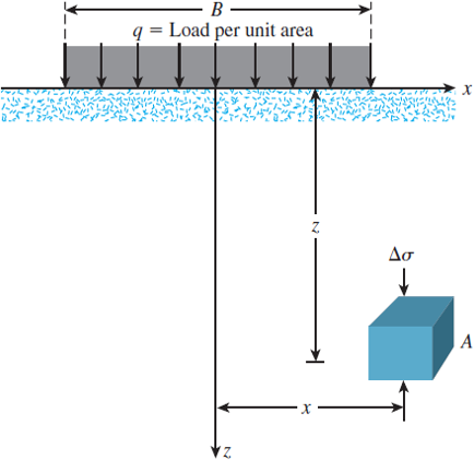
Figure P6.4
Expert Solution & Answer
Want to see the full answer?
Check out a sample textbook solution
Students have asked these similar questions
compute the load bearing capacity, displacement, stress distribution, tabulate the answers
compute the load bearing capacity, displacement, and stress distribution, tabulate the answers
compute the load bearing capacity, displacement, stress distribution, tabulate the answers
Chapter 6 Solutions
Principles of Foundation Engineering (MindTap Course List)
Ch. 6 - A flexible circular area is subjected to a...Ch. 6 - Point loads of magnitude 100, 200, and 400 kN act...Ch. 6 - Refer to Figure P6.3. Determine the vertical...Ch. 6 - Refer to Figure P6.4. A strip load of q = 900...Ch. 6 - Refer to Figure 6.6, which shows a flexible...Ch. 6 - Repeat Problem 6.5 with B1 = 4 ft, B2 = 10 ft, L1...Ch. 6 - Use Eq. (6.14) to determine the stress increase ()...Ch. 6 - Prob. 6.8PCh. 6 - Prob. 6.9PCh. 6 - Prob. 6.10P
Knowledge Booster


Learn more about
Need a deep-dive on the concept behind this application? Look no further. Learn more about this topic, civil-engineering and related others by exploring similar questions and additional content below.Similar questions
- By using the yield line theory, determine the ultimate resisting moment per linear meter (m) for an isotropic reinforced concrete two-way slab to sustain a concentrated factored load of P kN applied as shown in figure. Use equilibrium method in solution Column 2.0 P 8.0 m m m XXXXarrow_forwardBy using the yield line theory, determine the ultimate resisting moment (m) for an isotropic reinforced concrete two-way slab shown in figure under a uniform load (q). Use equilibrium method in solution m m column 20 m 20 marrow_forwardIn Tikrit city, environmental engineers are monitoring the diffusion of CO2 in the air as part of a pollution control study. The air-carbon dioxide mixture is at 295 K and 202.6 kPa, and the concentration of CO2 at two planes, 3 mm apart, is 25 vol.% at the first plane and 15 vol.% at the second plane. The diffusivity of CO2 in air under these conditions is 8.2 × 10⁶ m²/s. The study aims to calculate the rate of CO2 transfer across these two planes in two different scenarios: 1. What is the main engineering issue being addressed in this scenario? 2. Calculate the concentration of CO2 at the two planes in mol/m³ and determine the rate of transfer of CO2 using the diffusivity of CO2 in air. 3. With an engineering solution approach to solve the issue, calculate the rate of transfer of CO2 across the two planes assuming two scenarios: equimolecular counter diffusion and diffusion through a stagnant air layer. 4. Determine if there is a significant difference between the results of…arrow_forward
- Introduction: Orifice and Free Flow Jet in Applied Fluid Mechanics' I need to introduction only for answerarrow_forwardThe circular slab of radius 2 m supported by three columns, as shown in figure, is to be isotropically reinforced. Find the ultimate resisting moment per linear meter (m) required just to sustain a uniformly distributed load (q) equals 16 kN/m². Use equilibrium method in solution m Column marrow_forwardVehicles begin to arrive at a parking lot at 7:45 A.M. at a constant rate of 4 veh/min and continue to arrive at that rate throughout the day. The parking lot opens at 8:00 A.M. and vehicles are processed at a constant rate of one vehicle every 10 seconds. Assuming D/D/1 queuing, what is the longest queue, the queue at 8:15 A.M., and the average delay per vehicle from 7:45 A.M. until the queue clears?arrow_forward
- 1. Gunakan teor luasi momen untuk menentukan putaran sudut (slope) di B. Gunakan E = 200 GPa dan I-70 x 100 mm². m 8 kN·m B 2. Gunakan teori luas momen dan tentukan putaran sudut (slope) di A dan perpindahan di C. Gunakan E = 200 GPa dan I = 70 x 100 mm². 4 kN 4 kN -2 m 2 m- B 4 m 4 marrow_forwardConsider the conditions in Practice Problem 5.2. How short would the driver reaction times of oncoming vehicles have to be for the probability of an accident to equal 0.20?arrow_forwardPart 4: Problem-Solving. Solve the following problems. Show all calculations. 1. A Standard Penetration Test (SPT) was conducted at a site, and the following blow counts were recorded: Depth: 2 m, Blow count (N): 10 D D Depth: 4 m, Blow count (N): 15 Depth: 6 m, Blow count (N): 20 The energy ratio is 60%, and the overburden correction factor CN is 1.1. Calculate the corrected N-values for each depth. 2. A soil sample was collected from a depth of 3 m using a Shelby tube. The sample had a volume of 0.01 m³ and a mass of 18 kg. If the water content is 12%, calculate the (a) bulk density, (b) dry density, and (c) void ratio of the soil. Assume the specific gravity of soil solids (Gs) is 2.65. 3. A Cone Penetration Test (CPT) was conducted at a site, and the following data was obtained: Depth: 2 m, Cone resistance (qc): 5 MPa Depth: 4 m, Cone resistance (qc): 8 MPa Depth: 6 m, Cone resistance (qc): 12 MPa Estimate the soil type at each depth using typical qc correlations.arrow_forward
- Pls show step by step and formula usedarrow_forwardA: Wel Question 2 (a) A simple circular hollow section (CHS) tubular K-joint in a steel structure, subjected to balanced axial loading, is illustrated in Figure 2a. Determine the maximum hot spot stress at the joint intersection of the chord and the loaded brace B. (b) The steel structure is installed in the seawater with cathodic protection. Determine the number of stress cycles to failure based on the maximum hot stress range obtained in part (a). Use the NORSOK standard. (Refer to S-N curves for tubular joints in air environment and seawater with cathodic protection). (c) Estimate the number of load repetitions required to induce fatigue failure in the tubular joint, based on the load history provided in Figure 2b. The nominal yield and ultimate tensile strength are 355 N/mm² and 510 N/mm², respectively. Assume a damage limit of 1.0. Use the Modified Goodman formulation to determine the equivalent completely reversed stress. (d) Describe briefly the procedure to determine the hot…arrow_forwardThe steel member is a fillet welded built-up section that comprises two flange plates (100mm x 20mm) and a web plate (250mm x 10mm) as depicted in Section A-A. The leg size of the weld is 8 mm. Use an appropriate consequence class. Based on the damage tolerant method and the modified Goodman equation. Determine an equivalent completely reversed stress. Ignore the vibration and dynamic amplification. Use Euro-code 1993-1-9. (a) Calculate the maximum and minimum stresses at steel member section A-A. (b) Check the fatigue resistance of the steel member at Section A-A using the fatigue limit. (c) Discuss the possible failure mode of the steel member due to fatigue loading. State your design assumptions, if any. Steel plate (Flange) 100mm x 20mm 10.0 m Fillet weld (manual) (Typical) Steel plate (Web) 250mm x 10 mm Steel plate (Flange) 100mm x 20mm Section A-A Fixed end Welded built-up steel section 5.0 m A 2.5m 3.0 m Fatigue load range 5 kN A Total weight of steel section Total weight of…arrow_forward
arrow_back_ios
SEE MORE QUESTIONS
arrow_forward_ios
Recommended textbooks for you
 Principles of Foundation Engineering (MindTap Cou...Civil EngineeringISBN:9781305081550Author:Braja M. DasPublisher:Cengage Learning
 Principles of Geotechnical Engineering (MindTap C...Civil EngineeringISBN:9781305970939Author:Braja M. Das, Khaled SobhanPublisher:Cengage Learning
 Principles of Foundation Engineering (MindTap Cou...Civil EngineeringISBN:9781337705028Author:Braja M. Das, Nagaratnam SivakuganPublisher:Cengage Learning
 Fundamentals of Geotechnical Engineering (MindTap...Civil EngineeringISBN:9781305635180Author:Braja M. Das, Nagaratnam SivakuganPublisher:Cengage Learning
Principles of Foundation Engineering (MindTap Cou...
Civil Engineering
ISBN:9781305081550
Author:Braja M. Das
Publisher:Cengage Learning
Principles of Geotechnical Engineering (MindTap C...
Civil Engineering
ISBN:9781305970939
Author:Braja M. Das, Khaled Sobhan
Publisher:Cengage Learning
Principles of Foundation Engineering (MindTap Cou...
Civil Engineering
ISBN:9781337705028
Author:Braja M. Das, Nagaratnam Sivakugan
Publisher:Cengage Learning
Fundamentals of Geotechnical Engineering (MindTap...
Civil Engineering
ISBN:9781305635180
Author:Braja M. Das, Nagaratnam Sivakugan
Publisher:Cengage Learning
Stress Distribution in Soils GATE 2019 Civil | Boussinesq, Westergaard Theory; Author: Gradeup- GATE, ESE, PSUs Exam Preparation;https://www.youtube.com/watch?v=6e7yIx2VxI0;License: Standard YouTube License, CC-BY