
Principles of Foundation Engineering (MindTap Course List)
8th Edition
ISBN: 9781305081550
Author: Braja M. Das
Publisher: Cengage Learning
expand_more
expand_more
format_list_bulleted
Concept explainers
Videos
Textbook Question
Chapter 6, Problem 6.7P
Use Eq. (6.14) to determine the stress increase (Δσ) at z = 10 ft below the center of the area described in Problem 6.5.
6.5 Refer to Figure 6.6, which shows a flexible rectangular area. Given: B1 = 4 ft, B2 = 6 ft, L1, = 8 ft, and L2 = 10 ft. If the area is subjected to a uniform load of 3000 lb/ft2, determine the stress increase at a depth of 10 ft located immediately below point O.
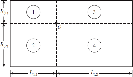
Figure 6.6 Stress below any point of a loaded flexible rectangular area
Expert Solution & Answer
Want to see the full answer?
Check out a sample textbook solution
Students have asked these similar questions
Pls show step by step and formula used
A:
Wel
Question 2
(a) A simple circular hollow section (CHS) tubular K-joint in a steel structure, subjected to balanced
axial loading, is illustrated in Figure 2a. Determine the maximum hot spot stress at the joint
intersection of the chord and the loaded brace B.
(b) The steel structure is installed in the seawater with cathodic protection. Determine the number of
stress cycles to failure based on the maximum hot stress range obtained in part (a). Use the
NORSOK standard. (Refer to S-N curves for tubular joints in air environment and seawater with
cathodic protection).
(c) Estimate the number of load repetitions required to induce fatigue failure in the tubular joint, based
on the load history provided in Figure 2b. The nominal yield and ultimate tensile strength are 355
N/mm² and 510 N/mm², respectively. Assume a damage limit of 1.0. Use the Modified Goodman
formulation to determine the equivalent completely reversed stress.
(d) Describe briefly the procedure to determine the hot…
The steel member is a fillet welded built-up section that comprises two flange plates (100mm x 20mm) and a
web plate (250mm x 10mm) as depicted in Section A-A. The leg size of the weld is 8 mm. Use an
appropriate consequence class. Based on the damage tolerant method and the modified Goodman equation.
Determine an equivalent completely reversed stress. Ignore the vibration and dynamic amplification. Use
Euro-code 1993-1-9.
(a) Calculate the maximum and minimum stresses at steel member section A-A.
(b) Check the fatigue resistance of the steel member at Section A-A using the fatigue limit.
(c) Discuss the possible failure mode of the steel member due to fatigue loading.
State your design assumptions, if any.
Steel plate (Flange)
100mm x 20mm
10.0 m
Fillet weld (manual)
(Typical)
Steel plate (Web)
250mm x 10 mm
Steel plate (Flange)
100mm x 20mm
Section A-A
Fixed end
Welded built-up
steel section
5.0 m
A
2.5m
3.0 m
Fatigue load range 5 kN
A
Total weight of steel section
Total weight of…
Chapter 6 Solutions
Principles of Foundation Engineering (MindTap Course List)
Ch. 6 - A flexible circular area is subjected to a...Ch. 6 - Point loads of magnitude 100, 200, and 400 kN act...Ch. 6 - Refer to Figure P6.3. Determine the vertical...Ch. 6 - Refer to Figure P6.4. A strip load of q = 900...Ch. 6 - Refer to Figure 6.6, which shows a flexible...Ch. 6 - Repeat Problem 6.5 with B1 = 4 ft, B2 = 10 ft, L1...Ch. 6 - Use Eq. (6.14) to determine the stress increase ()...Ch. 6 - Prob. 6.8PCh. 6 - Prob. 6.9PCh. 6 - Prob. 6.10P
Knowledge Booster


Learn more about
Need a deep-dive on the concept behind this application? Look no further. Learn more about this topic, civil-engineering and related others by exploring similar questions and additional content below.Similar questions
- 30 20 10 Stress N/mm² 0 -10 -20 -30 Time Question 1 A Grade S355 steel member, which forms part of the structural framework supporting a storage tank in a warehouse, is subjected to various loads, as shown in Figure 1. The yield and tensile strength of the steel member are 355 N/mm² and 510 N/mm², respectively. The steel member is subjected to axial tension due to its self-weight and appurtenances of 40.0kN. The 10.0kN storage tank is positioned 1.0 m from the centreline of the steel member, and it experiences a fatigue load range of 5.0kN. The steel member is a fillet welded built-up section that comprises two flange plates (100mm x 20mm) and a web plate (250mm x 10mm) as depicted in Section A-A. The leg size of the weld is 8 mm. Use an appropriate consequence class. Based on the damage tolerant method and the modified Goodman equation. Determine an equivalent completely reversed stress. Ignore the vibration and dynamic amplification. Use Euro-code 1993-1-9. (a) Calculate the maximum…arrow_forwardPlease do not use design aid - R. Show step by step and every formular usedarrow_forwardFollowing is the variation of the field standard penetration number (№60) in a sand deposit: Depth (m) N60 1.5 6 3 8 4.5 9 6 8 7.5 9 13 14 The groundwater table is located at a depth of 6 m. Given: the dry unit weight of sand from 0 to a depth of 6 m is 16 kN/m³, and the saturated unit weight of sand for depth 6 to 12 m is 18.2 kN/m². Use the relationship given in the equation CN = 1 σo/Pa 0.5 to calculate the corrected penetration numbers. (Round your answers to the nearest whole number.) Depth (m) Neo (N1)00 1.5 3 6 8 4.5 9 6 7.5 9 14 8 13arrow_forward
- 1,5 m 1,5 m A 1,6 KN F 0,8 m E 0,8 marrow_forward5.85 The flow pattern through the pipe contraction is as shown, and the Q of water is 60 cfs. For d = 2 ft and D = 6 ft, what is the pressure at point B if the pressure at point C is 3200 psf? D E Problem 5.85 20° Barrow_forwardPlease solve problem 8.13 (the highlighted question).arrow_forward
- The following figure shows a vertical retaining wall with a granular backfill: 100.0 50.0 40.0 30.0 20.0 10.0- 5.0- 4.0 3.0- 2.0- = +1 0.8 0.6 0.4 0.2 0.0 -0.2 -0.4 -0.6 -0.8 -0.9 1.0- 0 10 20 30 40 45 ' (deg) (a) Figure Caquot and Kerisel's solution for K 3 Let H = 4m, a = 17.5°, y = 17.5 kN/m³, ' = 35°, and 8' = 10°. For given values of ' and 8', R' = 0.53. Based on Caquot and Kerisel's solution, what would be the passive force per meter length of the wall? (Enter your answer to two significant figures.) Pp= kN/marrow_forwardThe dam presented below is 180 m long (in the direction perpendicular to the plane of thecross-section). For the water elevations given on the drawing:a) Construct the flow net (minimum number of equipotential lines should be 10),b) Calculate the rate of seepage for the entire dam,c) Find the total uplift force on the dam (ignore barriers), andd) Estimate the hydraulic gradient at points A, B, and Darrow_forwardThe influence line for moment at B for the beam shown is A -6 m- B a. O at A, 6 at B, and 15 at C b. 1 at A, 1 at B, and 1 at C c. O at A, 0 at B, and -9 at C d. O at A, 1 at B, and 1 and C -9 m-arrow_forward
- Consider the following figure: H/3 Pa Given: H = 7 m, y = 13 kN/m³, ø′ = 25°, c′ = 12 kN/m², and a = 10°. For given values, K₁ = 0.296. Calculate the Rankine active force per unit length of the wall after the occurrence of the tensile crack. (Enter your answer to three significant figures.) Pa = kN/marrow_forwardWall movement to left 45+ '/2 45 + 6'/2 Rotation of wall about this point A vertical retaining wall shown in the figure above is 7 m high with a horizontal backfill. For the backfill, assume that y = 14.5 kN/m³, ' = 26°, and c′ = 18 kN/m². Determine the Rankine active force per unit length of the wall after the occurrence of the tensile crack. (Enter your answer to three significant figures.) Pa = kN/marrow_forwardConsider the following figure: 0.6 "d 0.5 k₁ = 0 0.4 03 =0 kh = 0.2 0.3 0.025 0.2 0.05 0.1 0.1 0.2 0 -0.1 ↓ 0 5 10 15 20 25 30 35 40 45 ' (deg) For a retaining wall with a vertical back and horizontal backfill with a c'-' soil, the following are given: H = 10 ft Y = 111 lb/ft³ ' = 25° kh = 0.2 k₁ = 0 c = 113 lb/ft² Determine the magnitude of active force Pae on the wall. (Enter your answer to two significant figures.) Pae = lb/ftarrow_forward
arrow_back_ios
SEE MORE QUESTIONS
arrow_forward_ios
Recommended textbooks for you
 Principles of Geotechnical Engineering (MindTap C...Civil EngineeringISBN:9781305970939Author:Braja M. Das, Khaled SobhanPublisher:Cengage Learning
 Principles of Foundation Engineering (MindTap Cou...Civil EngineeringISBN:9781305081550Author:Braja M. DasPublisher:Cengage Learning
 Principles of Foundation Engineering (MindTap Cou...Civil EngineeringISBN:9781337705028Author:Braja M. Das, Nagaratnam SivakuganPublisher:Cengage Learning
 Fundamentals of Geotechnical Engineering (MindTap...Civil EngineeringISBN:9781305635180Author:Braja M. Das, Nagaratnam SivakuganPublisher:Cengage Learning
 Materials Science And Engineering PropertiesCivil EngineeringISBN:9781111988609Author:Charles GilmorePublisher:Cengage Learning
Principles of Geotechnical Engineering (MindTap C...
Civil Engineering
ISBN:9781305970939
Author:Braja M. Das, Khaled Sobhan
Publisher:Cengage Learning
Principles of Foundation Engineering (MindTap Cou...
Civil Engineering
ISBN:9781305081550
Author:Braja M. Das
Publisher:Cengage Learning
Principles of Foundation Engineering (MindTap Cou...
Civil Engineering
ISBN:9781337705028
Author:Braja M. Das, Nagaratnam Sivakugan
Publisher:Cengage Learning
Fundamentals of Geotechnical Engineering (MindTap...
Civil Engineering
ISBN:9781305635180
Author:Braja M. Das, Nagaratnam Sivakugan
Publisher:Cengage Learning
Materials Science And Engineering Properties
Civil Engineering
ISBN:9781111988609
Author:Charles Gilmore
Publisher:Cengage Learning
Stress Distribution in Soils GATE 2019 Civil | Boussinesq, Westergaard Theory; Author: Gradeup- GATE, ESE, PSUs Exam Preparation;https://www.youtube.com/watch?v=6e7yIx2VxI0;License: Standard YouTube License, CC-BY