
Concept explainers
Videos
(a)
Find the principal mass moment of inertia of the cylinder at the origin O.
(a)
Answer to Problem 9.183P
The principal moment of inertia are
Explanation of Solution
Given information:
Refer Problem 9.168.
Show the moment of inertia as follows:
Calculation:
Show the Equation 9.56 as follows:
Substitute
Consider the value of
Solve the above Equation and get the value of
The principal moment of inertia are
Thus, The principal moment of inertia are
(b)
Find the angles made by the principal axis of inertia at O with the coordinate axis.
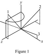
Sketch the body and show the orientation of the principal axis of inertia relative to x, y, and z axis.
(b)
Answer to Problem 9.183P
The angles made by the principal axis of inertia at O with the coordinate axis is,
Explanation of Solution
Given information:
Consider the direction cosines of each principal axis are denoted by
Calculation:
Refer Part (a).
Consider K1.
Show the Equation 9.54 as follows:
Substitute
Solve Equation (2).
Get the value of
Show the Equation 9.57 as follows:
Solve above Equation and get the value of
Show the direction cosines
Consider K2.
Show the Equation 9.54 as follows:
Substitute
Solve Equation (4).
Get the value of
Show the Equation 9.57 as follows:
Solve above Equation and get the value of
Show the direction cosines
Consider K3.
Show the Equation 9.54 as follows:
Substitute
Solve Equation (6).
Get the value of
Show the Equation 9.57 as follows:
Solve above Equation and get the value of
Show the direction cosines
The angles made by the principal axis of inertia at O with the coordinate axis is,
Sketch the body and show the orientation of the principal axis of inertia relative to x, y, and z axis as shown in Figure 1.
Want to see more full solutions like this?
Chapter 9 Solutions
Vector Mechanics for Engineers: Statics and Dynamics


- 11-5. Compute all the dimensional changes for the steel bar when subjected to the loads shown. The proportional limit of the steel is 230 MPa. 265 kN 100 mm 600 kN 25 mm thickness X Z 600 kN 450 mm E=207×103 MPa; μ= 0.25 265 kNarrow_forwardT₁ F Rd = 0.2 m md = 2 kg T₂ Tz1 Rc = 0.4 m mc = 5 kg m = 3 kgarrow_forward2. Find a basis of solutions by the Frobenius method. Try to identify the series as expansions of known functions. (x + 2)²y" + (x + 2)y' - y = 0 ; Hint: Let: z = x+2arrow_forward
- 1. Find a power series solution in powers of x. y" - y' + x²y = 0arrow_forward3. Find a basis of solutions by the Frobenius method. Try to identify the series as expansions of known functions. 8x2y" +10xy' + (x 1)y = 0 -arrow_forwardHello I was going over the solution for this probem and I'm a bit confused on the last part. Can you please explain to me 1^4 was used for the Co of the tubular cross section? Thank you!arrow_forward
- Blood (HD = 0.45 in large diameter tubes) is forced through hollow fiber tubes that are 20 µm in diameter.Equating the volumetric flowrate expressions from (1) assuming marginal zone theory and (2) using an apparentviscosity for the blood, estimate the marginal zone thickness at this diameter. The viscosity of plasma is 1.2 cParrow_forwardQ2: Find the shear load on bolt A for the connection shown in Figure 2. Dimensions are in mm Fig. 2 24 0-0 0-0 A 180kN (10 Markarrow_forwarddetermine the direction and magnitude of angular velocity ω3 of link CD in the four-bar linkage using the relative velocity graphical methodarrow_forward
- Four-bar linkage mechanism, AB=40mm, BC=60mm, CD=70mm, AD=80mm, =60°, w1=10rad/s. Determine the direction and magnitude of w3 using relative motion graphical method. A B 2 3 77777 477777arrow_forwardFour-bar linkage mechanism, AB=40mm, BC=60mm, CD=70mm, AD=80mm, =60°, w1=10rad/s. Determine the direction and magnitude of w3 using relative motion graphical method. A B 2 3 77777 477777arrow_forwardThe evaporator of a vapor compression refrigeration cycle utilizing R-123 as the refrigerant isbeing used to chill water. The evaporator is a shell and tube heat exchanger with the water flowingthrough the tubes. The water enters the heat exchanger at a temperature of 54°F. The approachtemperature difference of the evaporator is 3°R. The evaporating pressure of the refrigeration cycleis 4.8 psia and the condensing pressure is 75 psia. The refrigerant is flowing through the cycle witha flow rate of 18,000 lbm/hr. The R-123 leaves the evaporator as a saturated vapor and leaves thecondenser as a saturated liquid. Determine the following:a. The outlet temperature of the chilled waterb. The volumetric flow rate of the chilled water (gpm)c. The UA product of the evaporator (Btu/h-°F)d. The heat transfer rate between the refrigerant and the water (tons)arrow_forward
 Elements Of ElectromagneticsMechanical EngineeringISBN:9780190698614Author:Sadiku, Matthew N. O.Publisher:Oxford University Press
 Mechanics of Materials (10th Edition)Mechanical EngineeringISBN:9780134319650Author:Russell C. HibbelerPublisher:PEARSON
 Thermodynamics: An Engineering ApproachMechanical EngineeringISBN:9781259822674Author:Yunus A. Cengel Dr., Michael A. BolesPublisher:McGraw-Hill Education
 Control Systems EngineeringMechanical EngineeringISBN:9781118170519Author:Norman S. NisePublisher:WILEY
 Mechanics of Materials (MindTap Course List)Mechanical EngineeringISBN:9781337093347Author:Barry J. Goodno, James M. GerePublisher:Cengage Learning
 Engineering Mechanics: StaticsMechanical EngineeringISBN:9781118807330Author:James L. Meriam, L. G. Kraige, J. N. BoltonPublisher:WILEY