Vector Mechanics for Engineers: Statics and Dynamics
11th Edition
ISBN: 9780073398242
Author: Ferdinand P. Beer, E. Russell Johnston Jr., David Mazurek, Phillip J. Cornwell, Brian Self
Publisher: McGraw-Hill Education
bartleby

Concept explainers

bartleby

Videos

Question
Book Icon
Chapter 9.5, Problem 9.139P
To determine

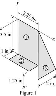
Find the mass moment of inertia of the anchor with respect to each of the coordinate axes.

Expert Solution & Answer
Check Mark

Answer to Problem 9.139P

The mass moment of inertia (Ix) of the anchor with respect to x axis is 344×106lbfts2_.

The mass moment of inertia (Iy) of the anchor with respect to y axis is 132.1×10⁶lbfts2_.

The mass moment of inertia (Iz) of the anchor with respect to z axis is 453×106lbfts2_.

Explanation of Solution

Given information:

The thickness (t) of the anchor is 0.05in.

The specific weight (γ) of the galvanized steel is 470lb/ft3.

Assume the acceleration due to gravity (g) as 32.2ft/s2

Calculation:

Show the section 1, section 2 and section 3 of the framing anchor as in Figure 1.

Vector Mechanics for Engineers: Statics and Dynamics, Chapter 9.5, Problem 9.139P

Calculate the density (ρ) of the galvanized steel using the relation:

ρ=γg

Substitute 470lb/ft3 for γ and 32.2ft/s2 for g.

ρ=47032.2=14.596lbs2/ft4

Calculate the volume of the section 1 (V1) using the relation:

V1=A1t=3.5×2.25×t

Substitute 0.05in. for t.

V1=3.5×2.25×0.05=0.39375in.3×(1ft12in.)3=2.2786×104ft3

Calculate the volume of the section 2 (V2) as below:

V2=A2t=1×2.25×t

Substitute 0.05in. for t.

V2=1×2.25×0.05=0.1125in.3×(1ft12in.)3=6.5104×105ft3

Calculate the volume (V3) of the section 3 as below:

V3=A3t=12(3.5+1.25)×2×t

Substitute 0.05in. for t.

V3=12×(3.5+1.25)×2×0.05=0.2375in.3×(1ft12in.)3=1.3744×104ft3

Calculate the mass of section 1 (m1) using the relation:

m1=ρV1

Substitute 2.2786×104ft3 for V1 and 14.596lbs2/ft4 for ρ.

m1=14.596×2.2786×104=3325.845×106lbs2/ft

Calculate the mass of section 2 (m2) using the relation:

m2=ρV2

Substitute 6.5104×105ft3 for V2 and 14.596lbs2/ft4 for ρ.

m2=14.596×6.5104×105=950.26×10⁶lbs2/ft

Calculate the mass of section 3 (m3) using the relation:

m3=ρV3

Substitute 1.3744×104ft3 for V3 and 14.596lbs2/ft4 for ρ.

m3=14.596×1.3744×104=2006.14×106lbs2/ft

Calculate the mass moment of inertia with respect to x axis for section 1 (Ix)1 as below:

(Ix)1=112(m1)(3.5)2+(m1×(3.52)2)

Substitute 3325.845×106lbs2/ft for m1.

(Ix)1=112(3325.845×106lbs2/ft)(3.5in.×1ft12in.)2+(3325.845×106lbs2/ft×((3.5in.)×1ft12in.2)2)=2.3577×105+7.073×105=9.4307×105lbfts2

Calculate the mass moment of inertia with respect to x axis for  section 2 (Ix)2 as below:

(Ix)2=112(m2)(1)2+(m2×(3.52+(12)2))

Substitute 950.26×10⁶lbs2/ft for m2.

(Ix)2=112(950.26×10⁶lbs2/ft)(1in.×1ft12in.)2+(950.26×106lbs2/ft× ((3.5in.×1ft12in.)2+((1in.×1ft12in.)2)2))=5.4992×10⁷+8.2488×105=83.037×10⁶lbfts2

Calculate the mass moment of inertia with respect to x axis for section 3 (Ix)3 as below:

(Ix)3=118(m3)((3.5+1.25)2+22)+(m3×((23(3.5+1.25))2+(13×2)2))

Substitute 2006.14×106lbs2/ft for m3.

(Ix)3=118(2006.14×106lbs2/ft)(((3.5+1.25)in.×1ft12in.)2+(2in.×1ft12in.)2)+ +(2006.14×106lbs2/ft×((23((3.5+1.25)in.×1ft12in.))2+(13×2in.×1ft12in.)2))=2.0558×105+1.4589×104=166.452×106lbfts2

Calculate the mass moment of inertia with respect to x axis for anchor (Ix) using the parallel axis theorem as below:

Ix=(Ix)1+(Ix)2+(Ix)3

Substitute 9.4307×10⁵lbfts2 for (Ix)1, 83.037×10⁶lbfts2 for (Ix)2 and 166.452×10⁶lbfts2 for (Ix)3.

Ix=9.4307×10⁵+83.037×10⁶+166.452×106=3.437×10⁴lbfts2344×106lbfts2

Calculate the mass moment of inertia with respect to y axis for section 1 (Iy)1 as below:

(Iy)1=112m1(2.25)2+m1(2.252)2

Substitute 3325.845×106lbs2/ft for m1.

(Iy)1={112×3325.845×106lbs2/ft×(2.25in.×1ft12in.)2 +3325.845×106lbs2/ft×((2.25in.×1ft12in.)2)2}=9.7436×106+2.923×105=38.975×106lbfts2

Calculate the mass moment of inertia with respect to y axis for section 2 (Iy)2 as below:

(Iy)2=112m2((2.25)2+(1)2)+m2[(2.252)2+(12)2]

Substitute 950.26×10⁶lbs2/ft for m2.

(Iy)2={112(950.26×10⁶lbs2/ft)((2.25in.×1ft12in.)2+(1in.×1ft12in.)2) +950.26×10⁶lbs2/ft[((2.25in.×1ft12in.)2)2+(1in.×1ft12in.2)2]}=3.334×106+1.00017×105=13.336×106lbfts2

Calculate the mass moment of inertia with respect to y axis for section 3 (Iy)3 as below:

(Iy)3=118m3(2)2+m3[2.252+(132)2]

Substitute 2006.14×106lbs2/ft for m3.

(Iy)3={118×2006.14×106lbs2/ft(2in.×1ft12in.)2 +2006.14×106lbs2/ft[(2.25in.×1ft12in.)2+(13×(2in.×1ft12in.))2]}=3.096×106+7.672×105=79.816×106lbfts2

Calculate the mass moment of inertia with respect to y axis for anchor (Iy) using the parallel axis theorem as below:

Iy=(Iy)1+(Iy)2+(Iy)3

Substitute 38.975×10⁶lbfts2 for (Iy)1 13.336×10⁶lbfts2 for (Iy)2 and 79.816×10⁶lbfts2 for (Iy)3.

Iy=38.975×10⁶+13.336×10⁶+79.816×106=132.127×10⁶lbfts2132.1×106lbfts2

Calculate the mass moment of inertia with respect to z axis for section 1 (Iz)1 as below:

(Iz)1=112m1[(2.25)2+(3.5)2]+m1[(2.252)2+(3.52)2]

Substitute 3325.845×106lbs2/ft for m1.

(Iz)1={1123325.845×106lbs2/ft[(2.25in.×1ft12in.)2+(3.5in.×1ft12in.)2] +3325.845×106lbs2/ft[(2.25in.×1ft12in.2)2+(3.5in.×1ft12in.2)2]}=3.332×105+9.996×105=133.283×106lbfts2

Calculate the mass moment of inertia with respect to z axis for section 2 (Ix)2 as below:

(Iz)2=112m2(2.25)2+m2[(2.252)2+(3.5)2]

Substitute 950.26×10⁶lbs2/ft for m2.

(Iz)2={112×950.26×106lbs2/ft×(2.25in.×1ft12in.)2 +950.26×10⁶lbs2/ft×[(2.25in.×1ft12in.2)2+(3.5in.×1ft12in.)2]}=2.784×106+8.918×105=91.974×106lbfts2

Calculate the mass moment of inertia with respect to z axis for section 3 (Iy)3 as below:

(Iz)3=118m3(3.5+1.25)2+m3[(2.25)2+(23(3.5+1.25))2]

Substitute 2006.14×106lbs2/ft for m3.

(Iz)3={118×2006.14×106lbs2/ft((3.5+1.25)in.×1ft12in.)2 +2006.14×106lbs2/ft×[(2.25in.×1ft12in.)2+(23((3.5+1.25)in.×1ft12in.))2]}=1.746×106+2.102×104=227.694×106lbfts2

Calculate the mass moment of inertia with respect to z axis for anchor (Ix) using the parallel axis theorem as below:

Iz=(Iz)1+(Iz)2+(Iz)3

Substitute 133.283×10⁶lbfts2 for (Iz)1 91.974×10⁶lbfts2 for (Iz)2 and 227.694×10⁵lbfts2 for (Iz)3.

Iz=133.283×10⁶+91.974×10⁶+2.27.694×106=452.951×10⁶lbfts2453×106lbfts2

Therefore, the mass moment of inertia (Ix) of the anchor with respect to x axis is 344×106lbfts2_.

Therefore, the mass moment of inertia (Iy) of the anchor with respect to y axis is 132.1×10⁶lbfts2_.

Therefore, the mass moment of inertia (Iz) of the anchor with respect to z axis is 453×106lbfts2_.

Want to see more full solutions like this?

Subscribe now to access step-by-step solutions to millions of textbook problems written by subject matter experts!
Students have asked these similar questions
20-4-2025 Exam-2-Tribology Q1: What are the assumptions of hydrodynamic lubrication theory: Q2: Explain with sketch the cycle or process of engine lubrication system-pressurized lubrication system Q3: A short bearing is designed to operate with an eccentricity ratio = 0. 7. The journal diameter is 60 mm, and its speed is 1300 r.p.m. The journal is supported by a short hydrodynamic bearing of length L/D = 0. 5, and clearance ratio C/R = 103. The radial load on the bearing is 9800 N. a. Find the Sommerfeld number. b. Find the minimum viscosity of the lubricant for operating at ε = 0.7 c. Select a lubricant if the average bearing operating temperature is 70°c Q4: Two parallel circular disks of 100 mm diameter have a clearance of Imm between them. Under load, the downward velocity of the upper disk is 2 m/s. At the same time, the lower disk is stationary. The clearance is full of SAE 40 oil at a temperature of 60°c. a. Find the load on the upper disk that results in the instantaneous…
Tribobolgy 15/2022 Monthly Exam. Automobile Eng. Dert 2nd Semster/3rd class Max. Mark: 100% 7. Viscosity of multi-grade oils (a) Reduces with temperature (c) is less sensitive to temperature (b) Increases with temperature (d) None of the above 8. In a hydrodynamic journal bearing if eccentricity ratio = 1, it means (a) Journal/shaft is subjected to no load and the rotational speed is very high. (b) Journal is subjected to no load and the rotational speed is moderate (c) Journal is subjected to very light load and the rotational speed is very high. (d) Journal is subjected to very high load and the rotational speed is negligible. Q4/ The journal speed of a 100mm diameter journal is 2500 rpm. The journal is supported by a short hydrodynamic bearing of length L=0.6D, eccentricity ratio = 0.75 and a clearance ratio C/R=0.001. The radial load on the bearing is 10 kN. The lubricant is SAE 30, and the operating temperature of the lubricant in the bearing is 700C. 1- Assume…
1 of 2 Monthly Exam. Automobile Eng. Dert 2nd Semster/3rd class Max. Mark: 100% Q1/A/ Compare between the long and short journal bearings B/ With the help of Stribeck's curve, discuss different regimes of lubrication. C/ Explain the importance of Tribology in the design of different machine elements Q2 /A/ According to the SAE viscosity grading system all engine oils are divided into two classes: monograde and multi-grade. Compare between them? B/What are the differences between grease and Synthetic oils C/ Explain the effect of eccentricity ratio & with respect to hydrodynamic journal bearing. Q3/A/ What are the major factors which affect the selection of lubricants? B/What are the criteria to classify sliding bearings? C/ Answer of the following: 1. According to the SAE viscosity classification, the oil (SAE 40) is lower viscosity than the oil (SAE 20) at the same temperature. (True or False) 2. For a slow speed-highly loaded bearing, used oils of high viscosity; while for high-speed…

Chapter 9 Solutions

Vector Mechanics for Engineers: Statics and Dynamics

Ch. 9.1 - Prob. 9.11PCh. 9.1 - Prob. 9.12PCh. 9.1 - Prob. 9.13PCh. 9.1 - 9.12 through 9.14 Determine by direct integration...Ch. 9.1 - Prob. 9.15PCh. 9.1 - Prob. 9.16PCh. 9.1 - Prob. 9.17PCh. 9.1 - Prob. 9.18PCh. 9.1 - Prob. 9.19PCh. 9.1 - Prob. 9.20PCh. 9.1 - Prob. 9.21PCh. 9.1 - Prob. 9.22PCh. 9.1 - Prob. 9.23PCh. 9.1 - 9.23 and 9.24 Determine the polar moment of...Ch. 9.1 - Prob. 9.25PCh. 9.1 - Prob. 9.26PCh. 9.1 - Prob. 9.27PCh. 9.1 - Prob. 9.28PCh. 9.1 - Prob. 9.29PCh. 9.1 - Prove that the centroidal polar moment of inertia...Ch. 9.2 - Prob. 9.31PCh. 9.2 - Prob. 9.32PCh. 9.2 - Prob. 9.33PCh. 9.2 - Prob. 9.34PCh. 9.2 - Prob. 9.35PCh. 9.2 - Prob. 9.36PCh. 9.2 - Prob. 9.37PCh. 9.2 - Prob. 9.38PCh. 9.2 - Prob. 9.39PCh. 9.2 - Prob. 9.40PCh. 9.2 - Prob. 9.41PCh. 9.2 - 9.41 through 9.44 Determine the moments of inertia...Ch. 9.2 - Prob. 9.43PCh. 9.2 - Prob. 9.44PCh. 9.2 - 9.45 and 9.46 Determine the polar moment of...Ch. 9.2 - Prob. 9.46PCh. 9.2 - Prob. 9.47PCh. 9.2 - 9.47 and 9.48 Determine the polar moment of...Ch. 9.2 - 9.49 Two channels and two plates are used to form...Ch. 9.2 - Prob. 9.50PCh. 9.2 - Prob. 9.51PCh. 9.2 - Two 20-mm steel plates are welded to a rolled S...Ch. 9.2 - A channel and a plate are welded together as shown...Ch. 9.2 - Prob. 9.54PCh. 9.2 - Two L76 76 6.4-mm angles are welded to a C250 ...Ch. 9.2 - Prob. 9.56PCh. 9.2 - Prob. 9.57PCh. 9.2 - 9.57 and 9.58 The panel shown forms the end of a...Ch. 9.2 - Prob. 9.59PCh. 9.2 - 9.60 The panel shown forms the end of a trough...Ch. 9.2 - Prob. 9.61PCh. 9.2 - Prob. 9.62PCh. 9.2 - Prob. 9.63PCh. 9.2 - Prob. 9.64PCh. 9.2 - Prob. 9.65PCh. 9.2 - Prob. 9.66PCh. 9.3 - 9.67 through 9.70 Determine by direct integration...Ch. 9.3 - Prob. 9.68PCh. 9.3 - Prob. 9.69PCh. 9.3 - Prob. 9.70PCh. 9.3 - Prob. 9.71PCh. 9.3 - Prob. 9.72PCh. 9.3 - Prob. 9.73PCh. 9.3 - 9.71 through 9.74 Using the parallel-axis theorem,...Ch. 9.3 - Prob. 9.75PCh. 9.3 - 9.75 through 9.78 Using the parallel-axis theorem,...Ch. 9.3 - Prob. 9.77PCh. 9.3 - Prob. 9.78PCh. 9.3 - Determine for the quarter ellipse of Prob. 9.67...Ch. 9.3 - Determine the moments of inertia and the product...Ch. 9.3 - Determine the moments of inertia and the product...Ch. 9.3 - 9.75 through 9.78 Using the parallel-axis theorem,...Ch. 9.3 - Determine the moments of inertia and the product...Ch. 9.3 - Determine the moments of inertia and the product...Ch. 9.3 - Prob. 9.85PCh. 9.3 - 9.86 through 9.88 For the area indicated,...Ch. 9.3 - Prob. 9.87PCh. 9.3 - Prob. 9.88PCh. 9.3 - Prob. 9.89PCh. 9.3 - 9.89 and 9.90 For the angle cross section...Ch. 9.4 - Using Mohrs circle, determine for the quarter...Ch. 9.4 - Using Mohrs circle, determine the moments of...Ch. 9.4 - Prob. 9.93PCh. 9.4 - Using Mohrs circle, determine the moments of...Ch. 9.4 - Using Mohrs circle, determine the moments of...Ch. 9.4 - Using Mohrs circle, determine the moments of...Ch. 9.4 - For the quarter ellipse of Prob. 9.67, use Mohrs...Ch. 9.4 - 9.98 though 9.102 Using Mohrs circle, determine...Ch. 9.4 - Prob. 9.99PCh. 9.4 - 9.98 though 9.102 Using Mohrs circle, determine...Ch. 9.4 - Prob. 9.101PCh. 9.4 - Prob. 9.102PCh. 9.4 - Prob. 9.103PCh. 9.4 - 9.104 and 9.105 Using Mohrs circle, determine the...Ch. 9.4 - 9.104 and 9.105 Using Mohrs circle, determine the...Ch. 9.4 - For a given area, the moments of inertia with...Ch. 9.4 - it is known that for a given area Iy = 48 106 mm4...Ch. 9.4 - Prob. 9.108PCh. 9.4 - Prob. 9.109PCh. 9.4 - Prob. 9.110PCh. 9.5 - A thin plate with a mass m is cut in the shape of...Ch. 9.5 - A ring with a mass m is cut from a thin uniform...Ch. 9.5 - Prob. 9.113PCh. 9.5 - The parabolic spandrel shown was cut from a thin,...Ch. 9.5 - Prob. 9.115PCh. 9.5 - Fig. P9.115 and P9.116 9.116 A piece of thin,...Ch. 9.5 - 9.117 A thin plate with a mass m has the...Ch. 9.5 - Prob. 9.118PCh. 9.5 - 9.119 Determine by direct integration the mass...Ch. 9.5 - The area shown is revolved about the x axis to...Ch. 9.5 - 9.121 The area shown is revolved about the x axis...Ch. 9.5 - Prob. 9.122PCh. 9.5 - Prob. 9.123PCh. 9.5 - Prob. 9.124PCh. 9.5 - Prob. 9.125PCh. 9.5 - Prob. 9.126PCh. 9.5 - Prob. 9.127PCh. 9.5 - Prob. 9.128PCh. 9.5 - Prob. 9.129PCh. 9.5 - Prob. 9.130PCh. 9.5 - Prob. 9.131PCh. 9.5 - The cups and the arms of an anemometer are...Ch. 9.5 - Prob. 9.133PCh. 9.5 - Determine the mass moment of inertia of the 0.9-lb...Ch. 9.5 - Prob. 9.135PCh. 9.5 - Prob. 9.136PCh. 9.5 - Prob. 9.137PCh. 9.5 - A section of sheet steel 0.03 in. thick is cut and...Ch. 9.5 - Prob. 9.139PCh. 9.5 - A farmer constructs a trough by welding a...Ch. 9.5 - The machine element shown is fabricated from...Ch. 9.5 - Determine the mass moments of inertia and the...Ch. 9.5 - Determine the mass moment of inertia of the steel...Ch. 9.5 - Prob. 9.144PCh. 9.5 - Determine the mass moment of inertia of the steel...Ch. 9.5 - Aluminum wire with a weight per unit length of...Ch. 9.5 - The figure shown is formed of 18-in.-diameter...Ch. 9.5 - A homogeneous wire with a mass per unit length of...Ch. 9.6 - Determine the mass products of inertia Ixy, Iyz,...Ch. 9.6 - Determine the mass products of inertia Ixy, Iyz,...Ch. 9.6 - Prob. 9.151PCh. 9.6 - Determine the mass products of inertia Ixy, Iyz,...Ch. 9.6 - 9.153 through 9.156 A section of sheet steel 2 mm...Ch. 9.6 - Prob. 9.154PCh. 9.6 - Prob. 9.155PCh. 9.6 - 9.153 through 9.156 A section of sheet steel 2 mm...Ch. 9.6 - Prob. 9.157PCh. 9.6 - Prob. 9.158PCh. 9.6 - Prob. 9.159PCh. 9.6 - Prob. 9.160PCh. 9.6 - Prob. 9.161PCh. 9.6 - For the homogeneous tetrahedron of mass m shown,...Ch. 9.6 - Prob. 9.163PCh. 9.6 - Prob. 9.164PCh. 9.6 - Prob. 9.165PCh. 9.6 - Determine the mass moment of inertia of the steel...Ch. 9.6 - Prob. 9.167PCh. 9.6 - Prob. 9.168PCh. 9.6 - Prob. 9.169PCh. 9.6 - 9.170 through 9.172 For the wire figure of the...Ch. 9.6 - Prob. 9.171PCh. 9.6 - Prob. 9.172PCh. 9.6 - Prob. 9.173PCh. 9.6 - Prob. 9.174PCh. 9.6 - Prob. 9.175PCh. 9.6 - Prob. 9.176PCh. 9.6 - Prob. 9.177PCh. 9.6 - Prob. 9.178PCh. 9.6 - Prob. 9.179PCh. 9.6 - Prob. 9.180PCh. 9.6 - Prob. 9.181PCh. 9.6 - Prob. 9.182PCh. 9.6 - Prob. 9.183PCh. 9.6 - Prob. 9.184PCh. 9 - Determine by direct integration the moments of...Ch. 9 - Determine the moment of inertia and the radius of...Ch. 9 - Prob. 9.187RPCh. 9 - Prob. 9.188RPCh. 9 - Prob. 9.189RPCh. 9 - Two L4 4 12-in. angles are welded to a steel...Ch. 9 - Prob. 9.191RPCh. 9 - Prob. 9.192RPCh. 9 - Prob. 9.193RPCh. 9 - Prob. 9.194RPCh. 9 - Prob. 9.195RPCh. 9 - Determine the mass moment of inertia of the steel...
Knowledge Booster
Background pattern image
Mechanical Engineering
Learn more about
Need a deep-dive on the concept behind this application? Look no further. Learn more about this topic, mechanical-engineering and related others by exploring similar questions and additional content below.
Similar questions
SEE MORE QUESTIONS
Recommended textbooks for you
Text book image
Elements Of Electromagnetics
Mechanical Engineering
ISBN:9780190698614
Author:Sadiku, Matthew N. O.
Publisher:Oxford University Press
Text book image
Mechanics of Materials (10th Edition)
Mechanical Engineering
ISBN:9780134319650
Author:Russell C. Hibbeler
Publisher:PEARSON
Text book image
Thermodynamics: An Engineering Approach
Mechanical Engineering
ISBN:9781259822674
Author:Yunus A. Cengel Dr., Michael A. Boles
Publisher:McGraw-Hill Education
Text book image
Control Systems Engineering
Mechanical Engineering
ISBN:9781118170519
Author:Norman S. Nise
Publisher:WILEY
Text book image
Mechanics of Materials (MindTap Course List)
Mechanical Engineering
ISBN:9781337093347
Author:Barry J. Goodno, James M. Gere
Publisher:Cengage Learning
Text book image
Engineering Mechanics: Statics
Mechanical Engineering
ISBN:9781118807330
Author:James L. Meriam, L. G. Kraige, J. N. Bolton
Publisher:WILEY
moment of inertia; Author: NCERT OFFICIAL;https://www.youtube.com/watch?v=A4KhJYrt4-s;License: Standard YouTube License, CC-BY