
Concept explainers
Videos
(a)
Find the principal moment of inertia at the origin O.
(a)
Answer to Problem 9.179P
The principal moment of inertia at the origin O is
Explanation of Solution
Given information:
The mass of the cylinder is denoted by m.
The length of the circular cylinder is denoted by a.
The diameter OB of the top surface makes
Calculation:
Show the homogeneous circular cylinder as shown in Figure 1.
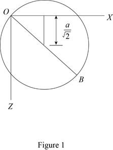
Refer Figure 1.
Refer Figure 9.28.
Apply parallel axis theorem
Show the moment of inertia of the circular cylinder about the y axis as follows:
Show the moment of inertia of the circular cylinder about the x and z axis as follows:
Here, a is the radius of the cylinder and L is the length of the cylinder.
Substitute
The centroidal axis products of inertia are zero due to symmetry.
Write the centroidal locations as measured from the origin O along the x, y and z axis as below;
Express the moment of inertia
Express the moment of inertia
Express the moment of inertia
Show the Equation 9.56 as follows:
Substitute
Substitute
Solve the above Equation and get the values of
Show the principal moment of inertia as follows:
Thus, the principal mass moment of inertia are
(b)
Find the angles made by the principal axis of inertia at O with the coordinate axis.
(b)
Answer to Problem 9.179P
The angles made by the principal axis of inertia at O with the coordinate axis is
Explanation of Solution
Given information:
Consider the direction cosines of each principal axis are denoted by
Calculation:
Refer Part (a).
Show the Equation 9.54 as follows:
Substitute
Modify Equation (3).
Consider
Solve Equation (4).
Add both the Equation in Equation (4).
Substitute
Show the Equation 9.57 as follows:
Substitute
Consider K1.
Substitute
Calculate the value of
Substitute
Show the direction cosines
Conisder K3.
Substitute
Calculate the value of
Substitute
Show the direction cosines
Consider K2.
Show the Equation 9.54b as follows:
Substitute
Refer Equation (3) and (6).
Substitute
Modify above Equations as follows:
Solve Equation (8) and get the value of
Show the Equation 9.57 as follows:
Substitute
Show the direction cosines
Thus, the velocity of the point B is
(c)
Sketch the body and show the orientation of the principal axis of inertia relative to x, y, and z axis.
(c)
Explanation of Solution
Given information:
Calculation:
Refer Part (a) and (b).
Sketch the body and show the orientation of the principal axis of inertia relative to x, y, and z axis as shown in Figure 2.
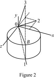
Refer Figure 2.
The principal axis 1 and 3 lies on the vertical plane of symmetry passing through OB.
The principal axis 2 lies in xz plane.
Want to see more full solutions like this?
Chapter 9 Solutions
Connect 1 Semester Access Card for Vector Mechanics for Engineers: Statics and Dynamics


- from this problem a want you to help to draw the shear moment and the bending momentarrow_forwardreaction at a is 1.6 wL (pos) handwritten solutions only please. correct answers upvotedarrow_forward1 8 4 Add numbers so that the sum of any row or column equals .30 Use only these numbers: .1.2.3.4.5.6.10.11.12.12.13.14.14arrow_forward
- Uppgift 2 (9p) I77777 20 kN 10 kN/m 4 [m] 2 2 Bestäm tvärkrafts- och momentdiagram för balken i figuren ovan. Extrempunkter ska anges med både läge och värde i diagrammen.arrow_forward**Problem 8-45.** The man has a mass of 60 kg and the crate has a mass of 100 kg. If the coefficient of static friction between his shoes and the ground is \( \mu_s = 0.4 \) and between the crate and the ground is \( \mu_c = 0.3 \), determine if the man is able to move the crate using the rope-and-pulley system shown. **Diagram Explanation:** The diagram illustrates a scenario where a man is attempting to pull a crate using a rope-and-pulley system. The setup is as follows: - **Crate (C):** Positioned on the ground with a rope attached. - **Rope:** Connects the crate to a pulley system and extends to the man. - **Pulley on Tree:** The rope runs over a pulley mounted on a tree which redirects the rope. - **Angles:** - The rope between the crate and tree forms a \(30^\circ\) angle with the horizontal. - The rope between the tree and the man makes a \(45^\circ\) angle with the horizontal. - **Man (A):** Pulling on the rope with the intention of moving the crate. This arrangement tests the…arrow_forwardplease solve this problems follow what the question are asking to do please show me step by steparrow_forward
- please help me to solve this problem and determine the stress for each point i like to be explained step by step with the correct answerarrow_forwardplease solve this problem for me the best way that you can explained to solve please show me the step how to solvearrow_forwardplese solbe this problem and give the correct answer solve step by step find the forces and line actionarrow_forward
 International Edition---engineering Mechanics: St...Mechanical EngineeringISBN:9781305501607Author:Andrew Pytel And Jaan KiusalaasPublisher:CENGAGE L