
Mechanics of Materials (10th Edition)
10th Edition
ISBN: 9780134319650
Author: Russell C. Hibbeler
Publisher: PEARSON
expand_more
expand_more
format_list_bulleted
Concept explainers
Videos
Textbook Question
thumb_up100%
Chapter 9.4, Problem 9.49P
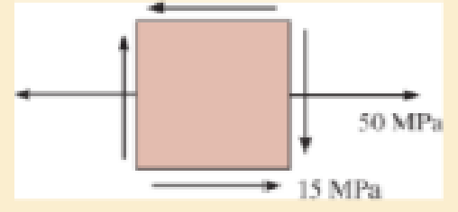
Solve Prob.9–16 using Mohr’s circle.
*9–16. Determine the equivalent state of stress on an element at the point which represents (a) the principal stresses and (b) the maximum in-plane shear stress and the associated average normal stress. Also, for each case, determine the corresponding orientation of the element with respect to the element shown and sketch the results on the element.
Expert Solution & Answer
Want to see the full answer?
Check out a sample textbook solution
Students have asked these similar questions
Solve this problem and show all of the work
Solve this problem and show all of the work
Solve this problem and show all of the work
Chapter 9 Solutions
Mechanics of Materials (10th Edition)
Ch. 9.3 - In each case, the state of stress x, y, xy...Ch. 9.3 - Given the state of stress shown on the element,...Ch. 9.3 - Determine the normal stress and shear stress...Ch. 9.3 - Determine the equivalent state of stress on an...Ch. 9.3 - Also, find the corresponding orientation of the...Ch. 9.3 - Determine the equivalent state of stress on an...Ch. 9.3 - Determine the maximum principal stress at point B.Ch. 9.3 - Determine the principal stress at point C.Ch. 9.3 - Prove that the sum of the normal stresses x + y =...Ch. 9.3 - Determine the stress components acting on the...
Ch. 9.3 - Determine the stress components acting on the...Ch. 9.3 - Determine the normal stress and shear stress...Ch. 9.3 - Determine the normal stress and shear stress...Ch. 9.3 - Determine the stress components acting on the...Ch. 9.3 - Determine the stress components acting on the...Ch. 9.3 - Solve Prob.97 using the stress transformation...Ch. 9.3 - Determine the stress components acting on the...Ch. 9.3 - Solve Prob.99 using the stress transformation...Ch. 9.3 - Determine the equivalent state of stress on an...Ch. 9.3 - Determine the equivalent slate of stress on an...Ch. 9.3 - Determine the stress components acting on the...Ch. 9.3 - Determine (a) the principal stresses and (b) the...Ch. 9.3 - The state of stress at a point is shown on the...Ch. 9.3 - Determine the equivalent state of stress on an...Ch. 9.3 - Determine the equivalent state of stress on an...Ch. 9.3 - A point on a thin plate is subjected to the two...Ch. 9.3 - Determine the equivalent state of stress on an...Ch. 9.3 - The stress along two planes at a point is...Ch. 9.3 - The stress acting on two planes at a point is...Ch. 9.3 - The state of stress at a point in a member is...Ch. 9.3 - The grains of wood in the board make an angle of...Ch. 9.3 - The wood beam is subjected to a load of 12 kN. If...Ch. 9.3 - The internal loadings at a section of the beam are...Ch. 9.3 - Solve Prob.925 for point B. 925. The internal...Ch. 9.3 - Solve Prob.925 for point C. 925. The internal...Ch. 9.3 - It is subjected to a torque of 12 kip in. and a...Ch. 9.3 - The bell crank is pinned at A and supported by a...Ch. 9.3 - The beam has a rectangular cross section and is...Ch. 9.3 - A paper tube is formed by rolling a cardboard...Ch. 9.3 - Solve Prob.931 for the normal stress acting...Ch. 9.3 - The 2-in.-diameter drive shaft AB on the...Ch. 9.3 - Determine the principal stresses in the...Ch. 9.3 - The internal loadings at a cross section through...Ch. 9.3 - The internal loadings at a cross section through...Ch. 9.3 - The shaft has a diameter d and is subjected to the...Ch. 9.3 - The steel pipe has an inner diameter of 2.75 in....Ch. 9.3 - Solve Prob.938 for point B, w1ich is located on...Ch. 9.3 - The wide-flange beam is subjected to the 50-kN...Ch. 9.3 - Solve Pro b. 9-40 for point B located on the web...Ch. 9.3 - The box beam is subjected to the 26-kN force that...Ch. 9.3 - Solve Prob.942 for point B. 942. The box beam is...Ch. 9.4 - Use Mohrs circle to determine the normal stress...Ch. 9.4 - Also, find the corresponding orientation of the...Ch. 9.4 - Draw Mohrs circle and determine the principal...Ch. 9.4 - Determine the principal stresses at a point on the...Ch. 9.4 - Determine the principal stresses at point A on the...Ch. 9.4 - Point A is just below the flange.Ch. 9.4 - Solve Prob.9-2 using Mohrs circle. 92. Determine...Ch. 9.4 - Solve Prob.93 using Mohrs circle. 93. Determine...Ch. 9.4 - Solve Prob.96 using Mohrs circle. 96. Determine...Ch. 9.4 - Solve Prob.911 using Mohrs circle. 911. Determine...Ch. 9.4 - Solve Prob.915 using Mohrs circle. 915. The state...Ch. 9.4 - Solve Prob.916 using Mohrs circle. 916. Determine...Ch. 9.4 - Mohrs circle for the state of stress is shown in...Ch. 9.4 - Determine (a) the principal stresses and (b) the...Ch. 9.4 - Determine (a) the principal stresses and (b) the...Ch. 9.4 - Determine the equivalent state of stress if an...Ch. 9.4 - Draw Mohrs circle that describes each of the...Ch. 9.4 - Draw Mohrs circle trial describes each of the...Ch. 9.4 - Determine (a) the principal stresses and (b) the...Ch. 9.4 - Determine (a) the principal stresses and (b) the...Ch. 9.4 - Determine (a) the principal stresses and (b) the...Ch. 9.4 - Determine (a) the principal stresses and (b) the...Ch. 9.4 - Determine (a) the principal stresses and (b) the...Ch. 9.4 - Draw Mohrs circle that describes each of the...Ch. 9.4 - The grains of wood in the board make an angle of...Ch. 9.4 - The post is fixed supported at its base and a...Ch. 9.4 - Determine the principal stresses, the maximum...Ch. 9.4 - The thin-walled pipe has an inner diameter of 0.5...Ch. 9.4 - The frame supports the triangular distributed load...Ch. 9.4 - The frame supports the triangular distributed load...Ch. 9.4 - The rotor shaft of the helicopter is subjected to...Ch. 9.4 - The pedal crank for a bicycle has the cross...Ch. 9.4 - A spherical pressure vessel has an inner radius of...Ch. 9.4 - The cylindrical pressure vessel has an inner...Ch. 9.4 - Determine the normal and shear stresses at point D...Ch. 9.4 - Determine the principal stress at point D, Which...Ch. 9.4 - If the box wrench is subjected to the 50 lb force,...Ch. 9.4 - If the box wrench is subjected to the 50-lb force,...Ch. 9.4 - The post is fixed supported at its base and the...Ch. 9.5 - Draw the three Mohrs circles that describe each of...Ch. 9.5 - Draw the three Mohrs circles that describe the...Ch. 9.5 - Draw the three Mohrs circles that describe the...Ch. 9.5 - Determine the principal stresses and the absolute...Ch. 9.5 - Determine the principal stresses and the absolute...Ch. 9.5 - Determine the principal stresses and the absolute...Ch. 9.5 - Determine the principal stresses and the absolute...Ch. 9.5 - The solid shaft is subjected to a torque, bending...Ch. 9.5 - The frame is subjected to a horizontal force and...Ch. 9.5 - The bolt is fixed to its support at C. If a force...Ch. 9.5 - The bolt is fixed to its support at C. If a force...Ch. 9 - Prob. 9.1RPCh. 9 - The steel pipe has an inner diameter of 2.75 in....Ch. 9 - Determine the equivalent state of stress If an...Ch. 9 - The crane is used to support the 350-lb load....Ch. 9 - Determine the equivalent state of stress on an...Ch. 9 - The propeller shaft of the tugboat is subjected to...Ch. 9 - Determine the principal stresses in the box beam...Ch. 9 - Determine (a) the principal stresses and (b) the...Ch. 9 - Determine the stress components acting on the...
Additional Engineering Textbook Solutions
Find more solutions based on key concepts
A nozzle at A discharges water with an initial velocity of 36 ft/s at an angle with the horizontal. Determine ...
Vector Mechanics For Engineers
Why is the study of database technology important?
Database Concepts (8th Edition)
Assume a telephone signal travels through a cable at two-thirds the speed of light. How long does it take the s...
Electric Circuits. (11th Edition)
17–1C A high-speed aircraft is cruising in still air. How does the temperature of air at the nose of the aircra...
Thermodynamics: An Engineering Approach
How are relationships between tables expressed in a relational database?
Modern Database Management
The following C++ program will not compile because the lines have been mixed up. cout Success\n; cout Success...
Starting Out with C++ from Control Structures to Objects (9th Edition)
Knowledge Booster


Learn more about
Need a deep-dive on the concept behind this application? Look no further. Learn more about this topic, mechanical-engineering and related others by exploring similar questions and additional content below.Similar questions
- Please do not rely too much on chatgpt, because its answer may be wrong. Please consider it carefully and give your own answer. You can borrow ideas from gpt, but please do not believe its answer.Very very grateful! Please do not copy other's work,i will be very very grateful!!Please do not copy other's work,i will be very very grateful!!arrow_forward= The frame shown is fitted with three 50 cm diameter frictionless pulleys. A force of F = 630 N is applied to the rope at an angle ◊ 43°. Member ABCD is attached to the wall by a fixed support at A. Find the forces indicated below. Note: The rope is tangent to the pully (D) and not secured at the 3 o'clock position. a b •C *су G E e d BY NC SA 2013 Michael Swanbom Values for dimensions on the figure are given in the following table. Note the figure may not be to scale. Variable Value a 81 cm b 50 cm с 59 cm d 155 cm For all answers, take x as positive to the right and positive upward. At point A, the fixed support exerts a force of: A = + ĴN and a reaction couple of: →> ΜΑ Member CG is in Select an answer magnitude У as k N-m. and carries a force of N.arrow_forwardThe lower jaw AB [Purple 1] and the upper jaw-handle AD [Yellow 2] exert vertical clamping forces on the object at R. The hand squeezes the upper jaw-handle AD [2] and the lower handle BC [Orane 4] with forces F. (Member CD [Red 3] acts as if it is pinned at D, but, in a real vise-grips, its position is actually adjustable.) The clamping force, R, depends on the geometry and on the squeezing force F applied to the handles. Determine the proportionality between the clamping force, R, and the squeezing force F for the dimensions given. d3 d4 R 1 B d1 2 d2 D... d5 F 4 F Values for dimensions on the figure are given in the following table. Note the figure may not be to scale. Variable Value d1 65 mm d2 156 mm d3 50 mm 45 d4 d5 113 mm 30 mm R = Farrow_forward
- A triangular distributed load of max intensity w =460 N/m acts on beam AB. The beam is supported by a pin at A and member CD, which is connected by pins at C and D respectively. Determine the reaction forces at A and C. Enter your answers in Cartesian components. Assume the masses of both beam AB and member CD are negligible. cc 040 BY NC SA 2016 Eric Davishahl W A C D -a- B Ул -b- x Values for dimensions on the figure are given in the following table. Note the figure may not be to scale. Variable Value α 5.4 m b 8.64 m C 3.24 m The reaction at A is A = i+ ĴN. λ = i+ Ĵ N. The reaction at C is C =arrow_forward56 Clamps like the one shown are commonly used in woodworking applications. This clamp has the dimensions given in the table below the figure, and its jaws are mm thick (in the direction perpendicular to the plane of the picture). a.) The screws of the clamp are adjusted so that there is a uniform pressure of P = 150 kPa being applied to the workpieces by the jaws. Determine the force carried in each screw. Hint: the uniform pressure can be modeled in 2-D as a uniform distributed load with intensity w = Pt (units of N/m) acting over the length of contact between the jaw and the workpiece. b.) Determine the minimum vertical force (parallel to the jaws) required to pull either one of the workpieces out of the clamp jaws. Use a coefficient of static friction between all contacting surfaces of μs = 0.56 and the same clamping pressure given for part (a). 2013 Michael Swanbom A B C a Values for dimensions on the figure are given in the following table. Note the figure may not be to scale.…arrow_forwardDetermine the force in each member of the space truss given F=5 kN. Use positive to indicate tension and negative to indicate compression. F E Z -2 m. B 3 m C 5 m 3 m A -4 m. AB = KN FAC = FAD = KN KN KN FBC = KN FBD FBE = = KN Farrow_forward
- A short brass cyclinder (denisty=8530 kg/m^3, cp=0.389 kJ/kgK, k=110 W/mK, and alpha=3.39*10^-5 m^2/s) of diameter 4 cm and height 20 cm is initially at uniform temperature of 150 degrees C. The cylinder is now placed in atmospheric air at 20 degrees C, where heat transfer takes place by convection with a heat transfer coefficent of 40 W/m^2K. Calculate (a) the center temp of the cylinder, (b) the center temp of the top surface of the cylinder, and (c) the total heat transfer from the cylinder 15 min after the start of the cooling. Solve this problem using the analytical one term approximation method. (Answer: (a) 45.7C, (b)45.3C, (c)87.2 kJ)arrow_forwardA short brass cyclinder (denisty=8530 kg/m^3, cp=0.389 kJ/kgK, k=110 W/mK, and alpha=3.39*10^-5 m^2/s) of diameter 4 cm and height 20 cm is initially at uniform temperature of 150 degrees C. The cylinder is now placed in atmospheric air at 20 degrees C, where heat transfer takes place by convection with a heat transfer coefficent of 40 W/m^2K. Calculate (a) the center temp of the cylinder, (b) the center temp of the top surface of the cylinder, and (c) the total heat transfer from the cylinder 15 min after the start of the cooling. Solve this problem using the analytical one term approximation method.arrow_forwardA 6 cm high rectangular ice block (k=2.22 W/mK, and alpha=0.124*10^-7 m^2/s) initially at -18 degrees C is placed on a table on its square base 4 cm by 4cm in size in a room at 18 degrees C. The heat transfer coefficent on the exposed surfaces of the ice block is 12 W/m^2K. Disregarding any heat transfer from the base to the table, determine how long it will be before the ice block starts melting. Where on the ice block will the first liquid droplets appear? Solve this problem using the analytical one-term approximation method.arrow_forward
- Consider a piece of steel undergoing a decarburization process at 925 degrees C. the mass diffusivity of carbon in steel at 925 degrees C is 1*10^-7 cm^2/s. Determine the depth below the surface of the steel at which the concentration of carbon is reduced to 40 percent from its initial value as a result of the decarburization process for (a) an hour and (b) 10 hours. Assume the concnetration of carbon at the surface is zero throughout the decarburization process.arrow_forwardPlease do not rely too much on chatgpt, because its answer may be wrong. Please consider it carefully and give your own answer. You can borrow ideas from gpt, but please do not believe its answer.Very very grateful! Please do not copy other's work,i will be very very grateful!!arrow_forwardMultiple Choice Circle the best answer to each statement. 1. Which geometry attribute deviation(s) can be limited with a profile of a surface tolerance? A. Location B. Orientation C. Form D. All of the above 2. A true profile may be defined with: A. Basic radii B. Basic angles C. Formulas D. All of the above 3. Which modifier may be applied to the profile tolerance value? A B C. D. All of the above 4. The default tolerance zone for a profile tolerance is: A. Non-uniform B. Unilateral C. Bilateral equal distribution D. Bilateral-unequal distribution 5. An advantage of using a profile tolerance in place of a coordinate tolerance is: A. A bonus tolerance is permitted. B. A datum feature sequence may be specified C. A profile tolerance always controls size D. All of the above 6. The shape of the tolerance zone for a profile tolerance is: A. Two parallel planes B. The same as the true profile of the toleranced surface C. Equal bilateral D. Cylindrical when the diameter symbol is speci- fied…arrow_forward
arrow_back_ios
SEE MORE QUESTIONS
arrow_forward_ios
Recommended textbooks for you
 Elements Of ElectromagneticsMechanical EngineeringISBN:9780190698614Author:Sadiku, Matthew N. O.Publisher:Oxford University Press
 Mechanics of Materials (10th Edition)Mechanical EngineeringISBN:9780134319650Author:Russell C. HibbelerPublisher:PEARSON
 Thermodynamics: An Engineering ApproachMechanical EngineeringISBN:9781259822674Author:Yunus A. Cengel Dr., Michael A. BolesPublisher:McGraw-Hill Education
 Control Systems EngineeringMechanical EngineeringISBN:9781118170519Author:Norman S. NisePublisher:WILEY
 Mechanics of Materials (MindTap Course List)Mechanical EngineeringISBN:9781337093347Author:Barry J. Goodno, James M. GerePublisher:Cengage Learning
 Engineering Mechanics: StaticsMechanical EngineeringISBN:9781118807330Author:James L. Meriam, L. G. Kraige, J. N. BoltonPublisher:WILEY
Elements Of Electromagnetics
Mechanical Engineering
ISBN:9780190698614
Author:Sadiku, Matthew N. O.
Publisher:Oxford University Press
Mechanics of Materials (10th Edition)
Mechanical Engineering
ISBN:9780134319650
Author:Russell C. Hibbeler
Publisher:PEARSON
Thermodynamics: An Engineering Approach
Mechanical Engineering
ISBN:9781259822674
Author:Yunus A. Cengel Dr., Michael A. Boles
Publisher:McGraw-Hill Education
Control Systems Engineering
Mechanical Engineering
ISBN:9781118170519
Author:Norman S. Nise
Publisher:WILEY
Mechanics of Materials (MindTap Course List)
Mechanical Engineering
ISBN:9781337093347
Author:Barry J. Goodno, James M. Gere
Publisher:Cengage Learning
Engineering Mechanics: Statics
Mechanical Engineering
ISBN:9781118807330
Author:James L. Meriam, L. G. Kraige, J. N. Bolton
Publisher:WILEY
Understanding Stress Transformation and Mohr's Circle; Author: The Efficient Engineer;https://www.youtube.com/watch?v=_DH3546mSCM;License: Standard youtube license