
Mechanics of Materials (10th Edition)
10th Edition
ISBN: 9780134319650
Author: Russell C. Hibbeler
Publisher: PEARSON
expand_more
expand_more
format_list_bulleted
Concept explainers
Videos
Textbook Question
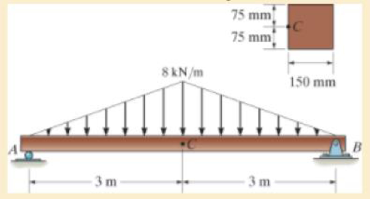
Chapter 9.3, Problem 9.6FP
Determine the principal stress at point C.
Expert Solution & Answer
Want to see the full answer?
Check out a sample textbook solution
Students have asked these similar questions
. A gas turbine with air enters the compressor at 300 K, 1 bar, and exits from the turbine at 750 K, 1 bar. The thermal efficiency of the cycle is 40.1% and the back work ratio (BWR) is 0.4. Find the pressure ratio of the cycle. Assume variable specific heat.
A regenerative gas turbine power plant is shown in Fig. below. Air enters the compressor at 1 bar, 27°C with a mass flow rate of 0.562 kg/s and is compressed to 4 bar. The isentropic efficiency of the compressor is 80%, and the regenerator effectiveness is 90%. All the power developed by the high-pressure turbine is used to run the compressor. The low-pressure turbine provides the net power output. Each turbine has an isentropic efficiency of 87% and the temperature at the inlet to the highpressure turbine is 1200 K. Assume cold air properties, determine:
a. The net power output, in kW.
b. The thermal efficiency of the cycle.
For tixed inlet state and exit pressure, use a cold-air standard analysis to show that the pressure ratio across the two compressor stages that gives nunimum work input is:=)) k/(k-1) when Ta Ti, where Ta is the temperature of the air entering the second stage compressor and Pi is the intercooler pressure. Put the suitable assumptions
Chapter 9 Solutions
Mechanics of Materials (10th Edition)
Ch. 9.3 - In each case, the state of stress x, y, xy...Ch. 9.3 - Given the state of stress shown on the element,...Ch. 9.3 - Determine the normal stress and shear stress...Ch. 9.3 - Determine the equivalent state of stress on an...Ch. 9.3 - Also, find the corresponding orientation of the...Ch. 9.3 - Determine the equivalent state of stress on an...Ch. 9.3 - Determine the maximum principal stress at point B.Ch. 9.3 - Determine the principal stress at point C.Ch. 9.3 - Prove that the sum of the normal stresses x + y =...Ch. 9.3 - Determine the stress components acting on the...
Ch. 9.3 - Determine the stress components acting on the...Ch. 9.3 - Determine the normal stress and shear stress...Ch. 9.3 - Determine the normal stress and shear stress...Ch. 9.3 - Determine the stress components acting on the...Ch. 9.3 - Determine the stress components acting on the...Ch. 9.3 - Solve Prob.97 using the stress transformation...Ch. 9.3 - Determine the stress components acting on the...Ch. 9.3 - Solve Prob.99 using the stress transformation...Ch. 9.3 - Determine the equivalent state of stress on an...Ch. 9.3 - Determine the equivalent slate of stress on an...Ch. 9.3 - Determine the stress components acting on the...Ch. 9.3 - Determine (a) the principal stresses and (b) the...Ch. 9.3 - The state of stress at a point is shown on the...Ch. 9.3 - Determine the equivalent state of stress on an...Ch. 9.3 - Determine the equivalent state of stress on an...Ch. 9.3 - A point on a thin plate is subjected to the two...Ch. 9.3 - Determine the equivalent state of stress on an...Ch. 9.3 - The stress along two planes at a point is...Ch. 9.3 - The stress acting on two planes at a point is...Ch. 9.3 - The state of stress at a point in a member is...Ch. 9.3 - The grains of wood in the board make an angle of...Ch. 9.3 - The wood beam is subjected to a load of 12 kN. If...Ch. 9.3 - The internal loadings at a section of the beam are...Ch. 9.3 - Solve Prob.925 for point B. 925. The internal...Ch. 9.3 - Solve Prob.925 for point C. 925. The internal...Ch. 9.3 - It is subjected to a torque of 12 kip in. and a...Ch. 9.3 - The bell crank is pinned at A and supported by a...Ch. 9.3 - The beam has a rectangular cross section and is...Ch. 9.3 - A paper tube is formed by rolling a cardboard...Ch. 9.3 - Solve Prob.931 for the normal stress acting...Ch. 9.3 - The 2-in.-diameter drive shaft AB on the...Ch. 9.3 - Determine the principal stresses in the...Ch. 9.3 - The internal loadings at a cross section through...Ch. 9.3 - The internal loadings at a cross section through...Ch. 9.3 - The shaft has a diameter d and is subjected to the...Ch. 9.3 - The steel pipe has an inner diameter of 2.75 in....Ch. 9.3 - Solve Prob.938 for point B, w1ich is located on...Ch. 9.3 - The wide-flange beam is subjected to the 50-kN...Ch. 9.3 - Solve Pro b. 9-40 for point B located on the web...Ch. 9.3 - The box beam is subjected to the 26-kN force that...Ch. 9.3 - Solve Prob.942 for point B. 942. The box beam is...Ch. 9.4 - Use Mohrs circle to determine the normal stress...Ch. 9.4 - Also, find the corresponding orientation of the...Ch. 9.4 - Draw Mohrs circle and determine the principal...Ch. 9.4 - Determine the principal stresses at a point on the...Ch. 9.4 - Determine the principal stresses at point A on the...Ch. 9.4 - Point A is just below the flange.Ch. 9.4 - Solve Prob.9-2 using Mohrs circle. 92. Determine...Ch. 9.4 - Solve Prob.93 using Mohrs circle. 93. Determine...Ch. 9.4 - Solve Prob.96 using Mohrs circle. 96. Determine...Ch. 9.4 - Solve Prob.911 using Mohrs circle. 911. Determine...Ch. 9.4 - Solve Prob.915 using Mohrs circle. 915. The state...Ch. 9.4 - Solve Prob.916 using Mohrs circle. 916. Determine...Ch. 9.4 - Mohrs circle for the state of stress is shown in...Ch. 9.4 - Determine (a) the principal stresses and (b) the...Ch. 9.4 - Determine (a) the principal stresses and (b) the...Ch. 9.4 - Determine the equivalent state of stress if an...Ch. 9.4 - Draw Mohrs circle that describes each of the...Ch. 9.4 - Draw Mohrs circle trial describes each of the...Ch. 9.4 - Determine (a) the principal stresses and (b) the...Ch. 9.4 - Determine (a) the principal stresses and (b) the...Ch. 9.4 - Determine (a) the principal stresses and (b) the...Ch. 9.4 - Determine (a) the principal stresses and (b) the...Ch. 9.4 - Determine (a) the principal stresses and (b) the...Ch. 9.4 - Draw Mohrs circle that describes each of the...Ch. 9.4 - The grains of wood in the board make an angle of...Ch. 9.4 - The post is fixed supported at its base and a...Ch. 9.4 - Determine the principal stresses, the maximum...Ch. 9.4 - The thin-walled pipe has an inner diameter of 0.5...Ch. 9.4 - The frame supports the triangular distributed load...Ch. 9.4 - The frame supports the triangular distributed load...Ch. 9.4 - The rotor shaft of the helicopter is subjected to...Ch. 9.4 - The pedal crank for a bicycle has the cross...Ch. 9.4 - A spherical pressure vessel has an inner radius of...Ch. 9.4 - The cylindrical pressure vessel has an inner...Ch. 9.4 - Determine the normal and shear stresses at point D...Ch. 9.4 - Determine the principal stress at point D, Which...Ch. 9.4 - If the box wrench is subjected to the 50 lb force,...Ch. 9.4 - If the box wrench is subjected to the 50-lb force,...Ch. 9.4 - The post is fixed supported at its base and the...Ch. 9.5 - Draw the three Mohrs circles that describe each of...Ch. 9.5 - Draw the three Mohrs circles that describe the...Ch. 9.5 - Draw the three Mohrs circles that describe the...Ch. 9.5 - Determine the principal stresses and the absolute...Ch. 9.5 - Determine the principal stresses and the absolute...Ch. 9.5 - Determine the principal stresses and the absolute...Ch. 9.5 - Determine the principal stresses and the absolute...Ch. 9.5 - The solid shaft is subjected to a torque, bending...Ch. 9.5 - The frame is subjected to a horizontal force and...Ch. 9.5 - The bolt is fixed to its support at C. If a force...Ch. 9.5 - The bolt is fixed to its support at C. If a force...Ch. 9 - Prob. 9.1RPCh. 9 - The steel pipe has an inner diameter of 2.75 in....Ch. 9 - Determine the equivalent state of stress If an...Ch. 9 - The crane is used to support the 350-lb load....Ch. 9 - Determine the equivalent state of stress on an...Ch. 9 - The propeller shaft of the tugboat is subjected to...Ch. 9 - Determine the principal stresses in the box beam...Ch. 9 - Determine (a) the principal stresses and (b) the...Ch. 9 - Determine the stress components acting on the...
Additional Engineering Textbook Solutions
Find more solutions based on key concepts
What is an uninitialized variable?
Starting Out with Programming Logic and Design (5th Edition) (What's New in Computer Science)
CONCEPT QUESTIONS
15.CQ3 The ball rolls without slipping on the fixed surface as shown. What is the direction ...
Vector Mechanics for Engineers: Statics and Dynamics
Why is the study of database technology important?
Database Concepts (8th Edition)
17–1C A high-speed aircraft is cruising in still air. How does the temperature of air at the nose of the aircra...
Thermodynamics: An Engineering Approach
How is the hydrodynamic entry length defined for flow in a pipe? Is the entry length longer in laminar or turbu...
Fluid Mechanics: Fundamentals and Applications
How are relationships between tables expressed in a relational database?
Modern Database Management
Knowledge Booster


Learn more about
Need a deep-dive on the concept behind this application? Look no further. Learn more about this topic, mechanical-engineering and related others by exploring similar questions and additional content below.Similar questions
- Derive the equation below ah ap ax 12μ ax, +( ah ap ay 12μ ay Where P P (x, y) is the oil film pressure. 1..ah 2 axarrow_forwardCan you determine the eignevalues by hand?arrow_forwardMonthly exam 13 2021-2022 Power plant Time: 1.5 Hrs Q1. A The gas-turbine cycle shown in Fig. is used as an automotive engine. In the first turbine, the gas expands to pressure Ps, just low enough for this turbine to drive the compressor. The gas is then expanded through the second turbine connected to the drive wheels. The data for the engine are shown in the figure, and assume that all processes are ideal. Determine the intermediate pressure Ps, the net specific work output of the engine, and the mass flow rate through the engine. Find also the air temperature entering the burner T3 and the thermal efficiency of the engine. Exhaust Air intake Φ www Regenerator www Bumer Compressor Turbine Power turbine et 150 kW Wompressor P₁ = 100 kPa T₁ = 300 K PP₁ =60 P-100 kPa T₁ = 1600 K Q2. On the basis of a cold air-standard analysis, show that the thermal efficiency of an ideal regenerative gas turbine can be expressed as 77 = 1- where - () () гp is the compressor pressure ratio, and T₁ and…arrow_forward
- I need to find m in R = mD from the image given. Do you really need to know what R and D is to find R. I was thinking geometrically we can find a relationship between R and D. D = R*cos(30). Then R = mD becomes m = R/D = 1/cos(30) = 1.1547. Is that correct?arrow_forwardQ1] B/ (16 Marks) To produce a lightweight epoxy part to provide thermal insulation. The available material are hollow glass beads for which the outside diameter is 1.6 mm and the wall thickness is 0.04 mm. Determine the weight and number of beads that must be added to the epoxy to produce a 0.5 kg of composite with a density of 0.65 g/cm³. The density of the glass is 2.5 g/cm³ and that of the epoxy is 1.25 g/cm³.arrow_forwardBelow is a projection of the inertia ellipsoid in the b1-b2 plane (b1 and b2 are unit vectors). All points on the ellipsoid surface represent moments of inertia in various directions. The distance R is related to the distance D such that R = md. Determine m.arrow_forward
- Below is a projection of the inertia ellipsoid in the b1-b2 plane (b1 and b2 are unit vectors). All points on the ellipsoid surface represent moments of inertia in various directions. Determine I_aa ( moment of inertia) for direction n_a (this is a unit vector).arrow_forwardThe problems are generally based on the following model: A particular spacecraft can be represented as a single axisymmetric rigid body B. Let n₂ be inertially fixed unit vectors; then, 6, are parallel to central, principal axes. To make the mathematics simpler, introduce a frame C where n₂ = ĉ₁ = b; initially. 6₁ Assume a mass distribution such that J =₁₁• B* •b₁ = 450 kg - m² I = b² •Ï¾˜ • b₂ = b¸ •Ï¾* •b¸ = 200 kg - m² K J-I C³ =r₁₁ = r₁₁arrow_forwardThe problems are generally based on the following model: A particular spacecraft can be represented as a single axisymmetric rigid body B. Let n₂ be inertially fixed unit vectors; then, 6, are parallel to central, principal axes. To make the mathematics simpler, introduce a frame C where n₂ = ĉ₁ = b; initially. 6₁ Assume a mass distribution such that J =₁₁• B* •b₁ = 450 kg - m² I = b² •Ï¾˜ • b₂ = b¸ •Ï¾* •b¸ = 200 kg - m² K J-I C³ =r₁₁ = r₁₁arrow_forward
- The problems are generally based on the following model: A particular spacecraft can be represented as a single axisymmetric rigid body B. Let n₂ be inertially fixed unit vectors; then, 6, are parallel to central, principal axes. To make the mathematics simpler, introduce a frame C where n₂ = ĉ₁ = b; initially. 6₁ Assume a mass distribution such that J =₁₁• B* •b₁ = 450 kg - m² I = b² •Ï¾˜ • b₂ = b¸ •Ï¾* •b¸ = 200 kg - m² K J-I C³ =r₁₁ = r₁₁arrow_forward##### Determine an example of a design of a compressed air system, which uses the criterion of speed for the design of the pipes (formula attached). The demands of flow rate, power as well as air velocity in the pipelines can be freely chosen. Sizing the compressor (flow, power...) Size reservoir required Setting the dryer Determine the amount of water withdrawn from the system due to air compression **With the attached formula you can choose the appropriate values of the unknownsarrow_forwardTo make an introduction to a report of a simple design of a compressed air system, which uses the criterion of speed, and not that of pressure drop, to determine the diameter of the pipes, where the capacity of the compressor and the demands of the equipment are expressed in flow.arrow_forward
arrow_back_ios
SEE MORE QUESTIONS
arrow_forward_ios
Recommended textbooks for you
 Elements Of ElectromagneticsMechanical EngineeringISBN:9780190698614Author:Sadiku, Matthew N. O.Publisher:Oxford University Press
 Mechanics of Materials (10th Edition)Mechanical EngineeringISBN:9780134319650Author:Russell C. HibbelerPublisher:PEARSON
 Thermodynamics: An Engineering ApproachMechanical EngineeringISBN:9781259822674Author:Yunus A. Cengel Dr., Michael A. BolesPublisher:McGraw-Hill Education
 Control Systems EngineeringMechanical EngineeringISBN:9781118170519Author:Norman S. NisePublisher:WILEY
 Mechanics of Materials (MindTap Course List)Mechanical EngineeringISBN:9781337093347Author:Barry J. Goodno, James M. GerePublisher:Cengage Learning
 Engineering Mechanics: StaticsMechanical EngineeringISBN:9781118807330Author:James L. Meriam, L. G. Kraige, J. N. BoltonPublisher:WILEY
Elements Of Electromagnetics
Mechanical Engineering
ISBN:9780190698614
Author:Sadiku, Matthew N. O.
Publisher:Oxford University Press
Mechanics of Materials (10th Edition)
Mechanical Engineering
ISBN:9780134319650
Author:Russell C. Hibbeler
Publisher:PEARSON
Thermodynamics: An Engineering Approach
Mechanical Engineering
ISBN:9781259822674
Author:Yunus A. Cengel Dr., Michael A. Boles
Publisher:McGraw-Hill Education
Control Systems Engineering
Mechanical Engineering
ISBN:9781118170519
Author:Norman S. Nise
Publisher:WILEY
Mechanics of Materials (MindTap Course List)
Mechanical Engineering
ISBN:9781337093347
Author:Barry J. Goodno, James M. Gere
Publisher:Cengage Learning
Engineering Mechanics: Statics
Mechanical Engineering
ISBN:9781118807330
Author:James L. Meriam, L. G. Kraige, J. N. Bolton
Publisher:WILEY
Understanding Stress Transformation and Mohr's Circle; Author: The Efficient Engineer;https://www.youtube.com/watch?v=_DH3546mSCM;License: Standard youtube license